Create simple brain activity monitor with INA114 and PIC18F2455
Your brain's story, captured in every wave
Published Jan 23, 2024
Click board™
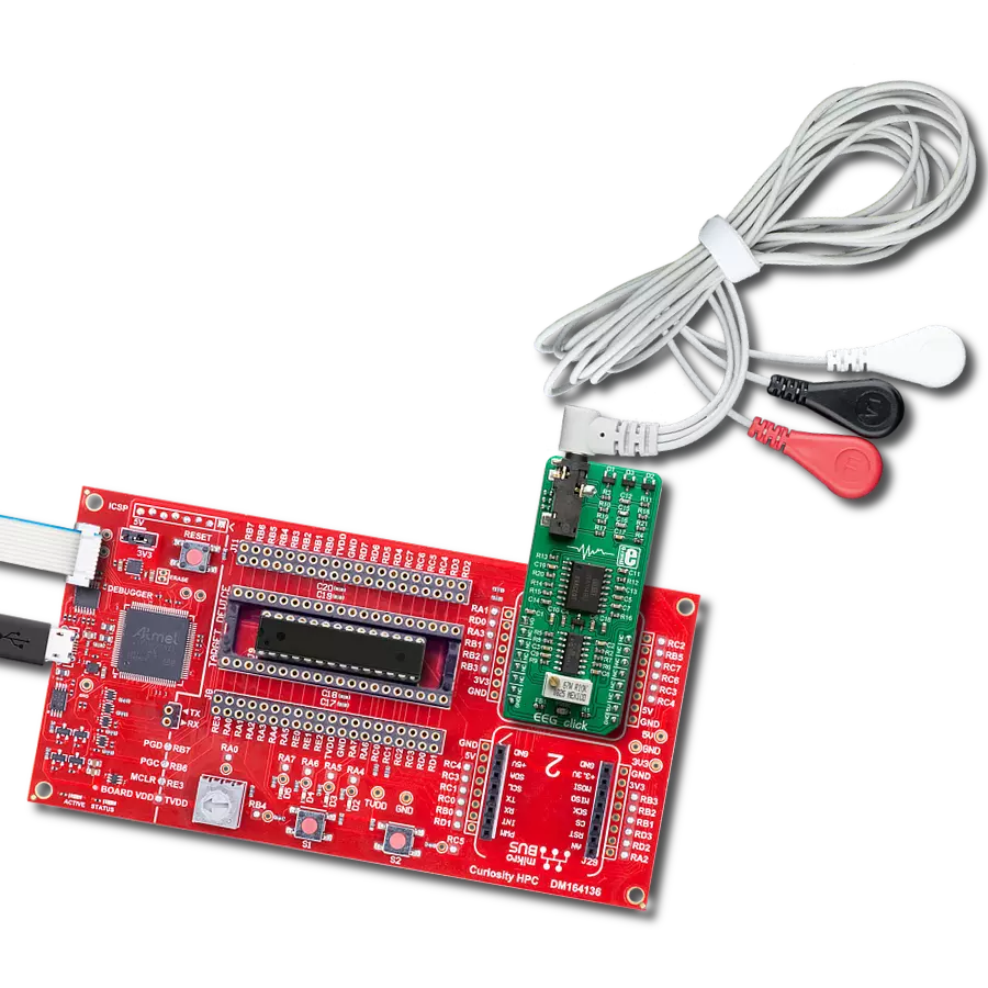
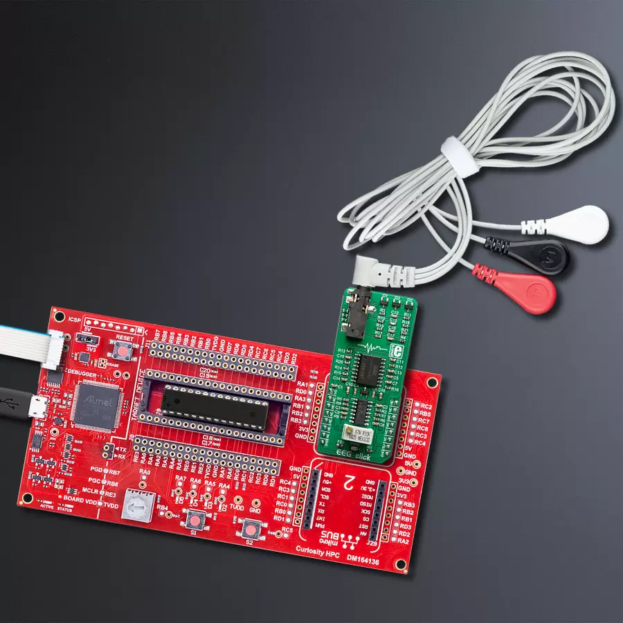
EEG Click
Dev. board
Curiosity HPC
Compiler
NECTO Studio
MCU
PIC18F2455
Unlock the secrets of brainwaves with our cutting-edge EEG technology
A
A
Hardware Overview
How does it work?
EEG Click is based on the INA114, a precision instrumentation amplifier (IA) by Burr Brown®, a division of Texas Instruments specialized in high-performance analog and mixed-signal ICs. This IC offers low noise, LASER-trimmed offset voltage, and a good common-mode rejection ratio. It uses a single resistor to set up its gain, which can easily be set up to 10,000. On this Click board™, the INA114 IA has its gain set to about 12 times. Further, amplification and signal filtering is done by the MCP609, a four-channel op-amp from Microchip, so that the final gain factor is about 7800 times. Such high amplification is necessary to amplify faint voltages generated during brain activity. To fine-tune the amplification, a multi-turn precision potentiometer allows for setting the gain of the intermediate amplification stage between
10 and 100 times. Since the "brain waves " can be both positive and negative, EEG click uses a virtual GND at the potential of 2.048V. This also helps to reduce the noise from the common GND, improving the quality of the readings. The amplified brain activity signal is available at the AN pin of the mikroBUS™, allowing sampling by the host MCU. EEG measurements should be ideally conducted in an electrically isolated room since any electromagnetic interference (EMI) could corrupt the measurement data. However, the INA114 offers some EMI protection, as it features an outstanding common-mode rejection ratio (CMRR), allowing it to cancel out most of the induced interferences successfully. This Click board™ uses a 3-electrode setup, which can be connected over a 3.5mm Jack connector on the
Click board™. Although the best results can be achieved using silver-chlorine-plated electrodes, any electrode can be used. EEG uses the DRL electrode placement scheme: two electrodes are placed behind the ears, while the third is placed on the forehead. The DRL electrode (on the forehead) helps eliminate the common voltage, while two other electrodes are connected to the differential inputs of the INA114 IA. The complete signal path is very well protected against voltage spikes and transients that might appear as a result of the electrostatic discharge (ESD) in contact with the human body, so there is a set of ESD suppressing diodes and TVS diodes, which prevent sensitive IA and operational amplifiers on its output to become damaged by ESD events.

Features overview
Development board
Curiosity HPC, standing for Curiosity High Pin Count (HPC) development board, supports 28- and 40-pin 8-bit PIC MCUs specially designed by Microchip for the needs of rapid development of embedded applications. This board has two unique PDIP sockets, surrounded by dual-row expansion headers, allowing connectivity to all pins on the populated PIC MCUs. It also contains a powerful onboard PICkit™ (PKOB), eliminating the need for an external programming/debugging tool, two mikroBUS™ sockets for Click board™ connectivity, a USB connector, a set of indicator LEDs, push button switches and a variable potentiometer. All
these features allow you to combine the strength of Microchip and Mikroe and create custom electronic solutions more efficiently than ever. Each part of the Curiosity HPC development board contains the components necessary for the most efficient operation of the same board. An integrated onboard PICkit™ (PKOB) allows low-voltage programming and in-circuit debugging for all supported devices. When used with the MPLAB® X Integrated Development Environment (IDE, version 3.0 or higher) or MPLAB® Xpress IDE, in-circuit debugging allows users to run, modify, and troubleshoot their custom software and hardware
quickly without the need for additional debugging tools. Besides, it includes a clean and regulated power supply block for the development board via the USB Micro-B connector, alongside all communication methods that mikroBUS™ itself supports. Curiosity HPC development board allows you to create a new application in just a few steps. Natively supported by Microchip software tools, it covers many aspects of prototyping thanks to many number of different Click boards™ (over a thousand boards), the number of which is growing daily.

Microcontroller Overview
MCU Card / MCU

Architecture
PIC
MCU Memory (KB)
24
Silicon Vendor
Microchip
Pin count
28
RAM (Bytes)
2048
You complete me!
Accessories
3-wire ECG/EMG cable comes with a convenient 3.5mm phone jack, and it is designed for electrocardiogram recording. This 1m cable is a practical companion for medical professionals and enthusiasts. To complement this cable, you can also use single-use adhesive ECG/EMG electrodes measuring 48x34mm, each equipped with an ECG/EMG cable stud adapter. These electrodes ensure a seamless experience when paired with our ECG/EMG cable and guarantee reliable ECG/EMG signal transmission for comprehensive cardiac monitoring. Trust in the accuracy and convenience of this setup to effortlessly record electrocardiograms and electromyograms with confidence.

Used MCU Pins
mikroBUS™ mapper
Take a closer look
Click board™ Schematic

Step by step
Project assembly

Start by selecting your development board and Click board™. Begin with the Curiosity HPC as your development board.


Software Support
Library Description
This library contains API for EEG Click driver.
Key functions:
eeg_read_an_pin_value- This function reads results of AD conversion of the AN pineeg_read_an_pin_voltage- This function reads results of AD conversion of the AN pin and converts them to proportional voltage level
Open Source
Code example
The complete application code and a ready-to-use project are available through the NECTO Studio Package Manager for direct installation in the NECTO Studio. The application code can also be found on the MIKROE GitHub account.
/*!
 * @file main.c
 * @brief EEG Click Example.
 *
 * # Description
 * This example demonstrates the use of EEG Click board.
 *
 * The demo application is composed of two sections :
 *
 * ## Application Init
 * Initializes Click board.
 *
 * ## Application Task
 * Reads ADC value and sends results on serial plotter every 5 ms.
 *
 * @author Jelena Milosavljevic
 *
 */

#include "board.h"
#include "log.h"
#include "eeg.h"

static eeg_t eeg;   /**< EEG Click driver object. */
static log_t logger;    /**< Logger object. */
uint32_t time = 0;

void application_init ( void )
{
    log_cfg_t log_cfg;  /**< Logger config object. */
    eeg_cfg_t eeg_cfg;  /**< Click config object. */

    /**
     * Logger initialization.
     * Default baud rate: 115200
     * Default log level: LOG_LEVEL_DEBUG
     * @note If USB_UART_RX and USB_UART_TX
     * are defined as HAL_PIN_NC, you will
     * need to define them manually for log to work.
     * See @b LOG_MAP_USB_UART macro definition for detailed explanation.
     */
    LOG_MAP_USB_UART( log_cfg );
    log_init( &logger, &log_cfg );
    log_info( &logger, " Application Init " );
    log_printf( &logger, " ----------------------------------------------\r\n" );
    log_printf( &logger, "                ***EEG Click***               \r\n" );
    log_printf( &logger, "----------------------------------------------\r\n" );
    Delay_ms ( 1000 );
    Delay_ms ( 1000 );

    // Click initialization.
    eeg_cfg_setup( &eeg_cfg );
    EEG_MAP_MIKROBUS( eeg_cfg, MIKROBUS_1 );
    if ( ADC_ERROR == eeg_init( &eeg, &eeg_cfg ) ){
        log_error( &logger, " Application Init Error. " );
        log_info( &logger, " Please, run program again... " );

        for ( ; ; );
    }
    log_info( &logger, " Application Task " );
}

void application_task ( void )
{
    uint16_t eeg_an_value = 0;

    if ( eeg_read_an_pin_value( &eeg, &eeg_an_value ) != ADC_ERROR ) {
        log_printf( &logger, " %u,%lu\r\n", eeg_an_value, time );
        Delay_ms ( 5 );
        time += 5;
    }
}

int main ( void )
{
    /* Do not remove this line or clock might not be set correctly. */
    #ifdef PREINIT_SUPPORTED
    preinit();
    #endif

    application_init( );

    for ( ; ; )
    {
        application_task( );
    }

    return 0;
}

// ------------------------------------------------------------------------ END
Additional Support
Resources
Category:Biometrics


