Your heart's storyteller based on the MAX30003 and PIC18F57Q43
ECG excellence for a healthier tomorrow
Published Feb 13, 2024
Click board™
ECG 3 Click
Dev. board
Curiosity Nano with PIC18F57Q43
Compiler
NECTO Studio
MCU
PIC18F57Q43
Experience the next generation of heart monitoring with our ECG solution
A
A
Hardware Overview
How does it work?
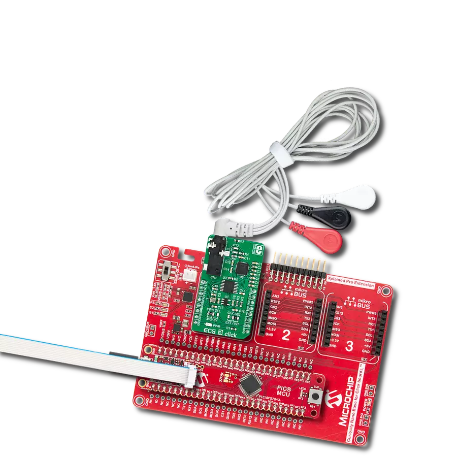
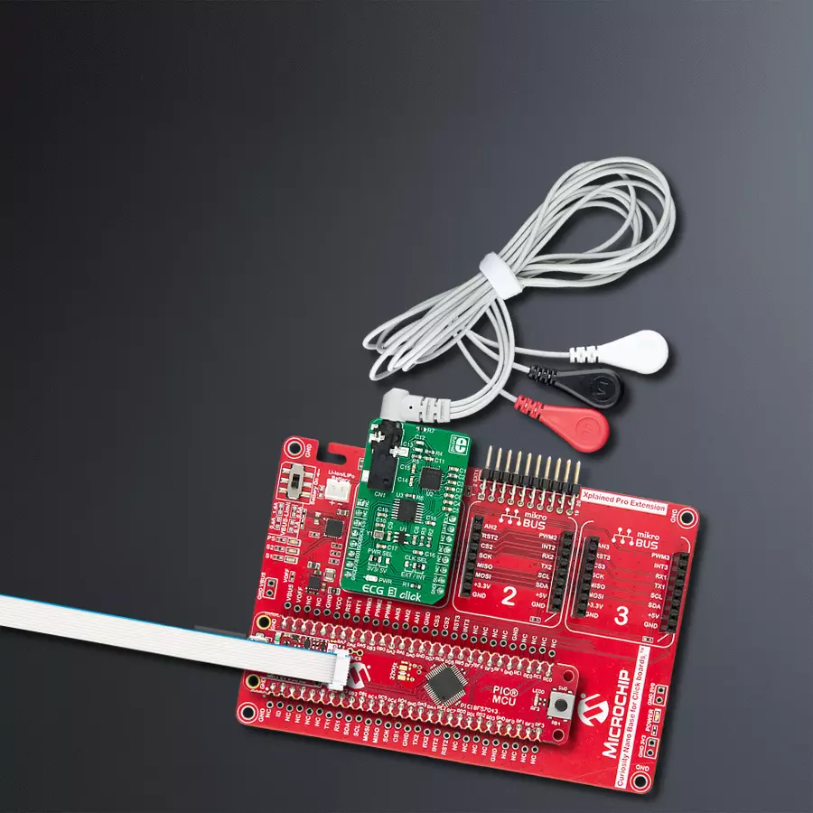
ECG 3 Click is equipped with the MAX30003, an ultra-low power, single channel, integrated biopotential AFE, with the ECG and R-to-R detection functionality from Analog Devices. ECG 3 click is used to record a single-channel electrocardiogram. Electrodes can be attached to ECG 3 click via the onboard 3.5mm jack. ECG 3 click uses a three-electrode system, where two electrodes are connected to the positive and negative differential input of the MAX30003 (ECGP and ECGN pins), while the third electrode is connected to the GND. The Click board™ can be used with the cable and electrodes such as these: ECG/EMG cable and ECG/EMG electrodes. In this case, the white electrode is the GND electrode. These voltage impulses are naturally weak and in the range of just a few millivolts. Therefore, any interferences might obscure them, making them undetectable. These interferences might be induced in the human body itself or appear as the result of the activity of other muscles, such as skeletal muscles. The MAX30003 is armed with several methods to reduce these interferences. However, the placement of the measurement electrodes is also crucial for accurate readings. The MAX30003 IC has two differential inputs comprising a single ECG channel. Therefore, the heart can be monitored from a single plane only - the coronal plane. However, this is quite enough for fitness, heart rate monitoring, and similar applications. All the mentioned features are mostly related to conditioning the input signal and protecting the IC from voltage surges, so several types of electrodes can be used. The inputs are equipped with a single-pole, high-pass (HP) EMI filter, with the cutoff frequency set to 2MHz,
as the first defense against the interferences. A set of integrated clamping diodes prevent the ESD surges from reaching the IC and damaging it. The inputs are connected with the electrodes over the protective serial switches, which are turned off by default. When developing your own application, care should be taken to turn these switches ON. However, the mikroSDK library functions included with the Click board™ take care of the proper configuring and initialization. The differential inputs are further amplified by an integrated low-noise, high-impedance instrumentation amplifier (IA) with a fixed gain. The IA section features yet another HP filter that helps to reject movement artifacts generated by skeletal muscles. Depending on the application requirements, a higher cutoff frequency will result in a less accurate ECG signal, but the effects of the motion artifacts will be reduced even more. This frequency is determined by a capacitor between the CAPP and CAPN pins of the MAX30003 IC, which is about 0.04Hz, with the 1uF capacitor used on the ECG 3 click. The recommended range for the HP cutoff frequency is from 0.04Hz up to 4.4Hz. Following the IA section, the MAX30003 incorporates the two-pole low-pass anti-aliasing (LP) filter with a cutoff frequency of 600Hz, which ensures good sampling quality. The programmable gain amplifier is the next section in the signal chain, allowing optimal signal amplitudes to reach the next stage - the sigma-delta 18-bit A/D converter, which ultimately generates the heart rate readings over the SPI interface. Other features of the MAX30003 IC include the self-testing programmable voltage sources and no lead detection. One of the key
features of the AFE is the R - R interval detection. R-wave is a part of the heart rate signal with the highest peak. The distance between the two peaks is closely related to the heart rate and can give a good insight into the shape of the R-wave when no plot is available. Closely matched R - R and BPM values indicate that R waves are quite sharp, without irregularities. Also, the BMP (beats per minute) is an average value, while the R - R interval represents the timing between two peaks. The extensive interrupt engine can trigger the host MCU from various sources, including interrupt events due to lead detection, R-R detection, fast-recovery event, FIFO buffer states, and many more. These interrupt sources can trigger a state change on the interrupt pin (INTB) of the MAX30003 IC. This pin is active-low. The MAX30003 IC requires a clock signal provided by the onboard oscillator. The frequency of the oscillator is 32.768 kHz. However, the Click board™ accepts the external clock signal over the PWM pin of the mikroBUS™, labeled as CLK. Regarding the voltage levels, there is a TXB0106 IC implemented on the ECG 3 Click, allowing it to operate with both 3.3V and 5V MCUs. This IC is a bi-directional voltage-level translator from Texas Instruments. It is a proven solution used on many different Click board™ designs, which transforms voltages of the logic signals (SPI, interrupt, clock) to 1.8V-level signals, which is acceptable for the MAX30003 IC. This allows many different MCUs to be interfaced with the ECG 3 click The logic voltage selection can be done with the onboard SMD jumper labeled as PWR SEL, while the clock source can be selected by another SMD jumper labeled as CLK SEL.

Features overview
Development board
PIC18F57Q43 Curiosity Nano evaluation kit is a cutting-edge hardware platform designed to evaluate microcontrollers within the PIC18-Q43 family. Central to its design is the inclusion of the powerful PIC18F57Q43 microcontroller (MCU), offering advanced functionalities and robust performance. Key features of this evaluation kit include a yellow user LED and a responsive
mechanical user switch, providing seamless interaction and testing. The provision for a 32.768kHz crystal footprint ensures precision timing capabilities. With an onboard debugger boasting a green power and status LED, programming and debugging become intuitive and efficient. Further enhancing its utility is the Virtual serial port (CDC) and a debug GPIO channel (DGI
GPIO), offering extensive connectivity options. Powered via USB, this kit boasts an adjustable target voltage feature facilitated by the MIC5353 LDO regulator, ensuring stable operation with an output voltage ranging from 1.8V to 5.1V, with a maximum output current of 500mA, subject to ambient temperature and voltage constraints.

Microcontroller Overview
MCU Card / MCU

Architecture
PIC
MCU Memory (KB)
128
Silicon Vendor
Microchip
Pin count
48
RAM (Bytes)
8196
You complete me!
Accessories
Curiosity Nano Base for Click boards is a versatile hardware extension platform created to streamline the integration between Curiosity Nano kits and extension boards, tailored explicitly for the mikroBUS™-standardized Click boards and Xplained Pro extension boards. This innovative base board (shield) offers seamless connectivity and expansion possibilities, simplifying experimentation and development. Key features include USB power compatibility from the Curiosity Nano kit, alongside an alternative external power input option for enhanced flexibility. The onboard Li-Ion/LiPo charger and management circuit ensure smooth operation for battery-powered applications, simplifying usage and management. Moreover, the base incorporates a fixed 3.3V PSU dedicated to target and mikroBUS™ power rails, alongside a fixed 5.0V boost converter catering to 5V power rails of mikroBUS™ sockets, providing stable power delivery for various connected devices.

3-wire ECG/EMG cable comes with a convenient 3.5mm phone jack, and it is designed for electrocardiogram recording. This 1m cable is a practical companion for medical professionals and enthusiasts. To complement this cable, you can also use single-use adhesive ECG/EMG electrodes measuring 48x34mm, each equipped with an ECG/EMG cable stud adapter. These electrodes ensure a seamless experience when paired with our ECG/EMG cable and guarantee reliable ECG/EMG signal transmission for comprehensive cardiac monitoring. Trust in the accuracy and convenience of this setup to effortlessly record electrocardiograms and electromyograms with confidence.

Used MCU Pins
mikroBUS™ mapper
Take a closer look
Click board™ Schematic

Step by step
Project assembly

Start by selecting your development board and Click board™. Begin with the Curiosity Nano with PIC18F57Q43 as your development board.


Software Support
Library Description
This library contains API for ECG 3 Click driver.
Key functions:
ecg3_get_ecg- Function reads ECG data from FIFO registerecg3_check_status- Function checks a status flag for the desired interruptecg3_get_rtor- Function reads Heart Rate and R - R data and calculates HR data to BPM, and RR data to ms
Open Source
Code example
The complete application code and a ready-to-use project are available through the NECTO Studio Package Manager for direct installation in the NECTO Studio. The application code can also be found on the MIKROE GitHub account.
/*!
 * \file
 * \brief Ecg3 Click example
 *
 * # Description
 * This Click is made for ECG and HR,
 * equipped with an ultra-low power, single channel, integrated biopotential AFE,
 * with the ECG and R-to-R detection functionality.
 *
 * The demo application is composed of two sections :
 *
 * ## Application Init
 * Initializes SPI interface and performs the all necessary configuration
 * for device to work properly.
 *
 * ## Application Task
 * Reads ECG Data every 8ms and sends this data to the serial plotter.
 *
 * *note:*
 * Additional Functions :
 *  - void plot_ecg() - Sends ECG Data to the serial plotter.
 *  - void log_rtor() - Sends Heart Rate and R - R Data to the uart terminal.
 *
 * \author MikroE Team
 *
 */
// ------------------------------------------------------------------- INCLUDES

#include "board.h"
#include "log.h"
#include "ecg3.h"

// ------------------------------------------------------------------ VARIABLES

static ecg3_t ecg3;
static log_t logger;

static uint32_t ecg_data;
static uint16_t rr_data;
static uint16_t hr_data;
static uint32_t meas_time_cnt = 0;

// ------------------------------------------------------- ADDITIONAL FUNCTIONS

void plot_ecg ( )
{
    if ( ecg_data > 50000 )
    {
        log_printf( &logger,"    %lu,       %lu\r\n", ecg_data, meas_time_cnt );

        if ( meas_time_cnt == 0xFFFFFFFF )
        {
            meas_time_cnt = 0;
        }
        else
        {
            meas_time_cnt++;
        }
    }
    Delay_ms ( 8 );
}

void log_rtor ( )
{
    if ( ( rr_data != 0 ) && ( hr_data != 65535 ) )
    {
        log_printf( &logger,"R - R Interval : %u ms\r\n", rr_data );
        log_printf( &logger,"Heart Rate :  %u BPM\r\n", hr_data );
    }
    Delay_ms ( 1000 );
    Delay_ms ( 1000 );
}

// ------------------------------------------------------ APPLICATION FUNCTIONS

void application_init ( void )
{
    log_cfg_t log_cfg;
    ecg3_cfg_t cfg;

    /**
     * Logger initialization.
     * Default baud rate: 115200
     * Default log level: LOG_LEVEL_DEBUG
     * @note If USB_UART_RX and USB_UART_TX
     * are defined as HAL_PIN_NC, you will
     * need to define them manually for log to work.
     * See @b LOG_MAP_USB_UART macro definition for detailed explanation.
     */
    LOG_MAP_USB_UART( log_cfg );
    log_init( &logger, &log_cfg );
    log_info( &logger, "---- Application Init ----" );

    //  Click initialization.

    ecg3_cfg_setup( &cfg );
    ECG3_MAP_MIKROBUS( cfg, MIKROBUS_1 );
    ecg3_init( &ecg3, &cfg );

    ecg3_sw_reset( &ecg3 );
    ecg3_fifo_reset( &ecg3 );
    Delay_ms ( 100 );

    ecg3_default_cfg ( &ecg3 );
    Delay_ms ( 300 );
}

void application_task ( void )
{
    ecg3_get_ecg( &ecg3, &ecg_data );

    plot_ecg( );
}

int main ( void )
{
    /* Do not remove this line or clock might not be set correctly. */
    #ifdef PREINIT_SUPPORTED
    preinit();
    #endif

    application_init( );

    for ( ; ; )
    {
        application_task( );
    }

    return 0;
}


// ------------------------------------------------------------------------ END
Additional Support
Resources
Category:Biometrics


