Create the perfect climate for your success with ENS210 and ATmega328P
Be in sync with nature's rhythm
Published Feb 14, 2024
Click board™
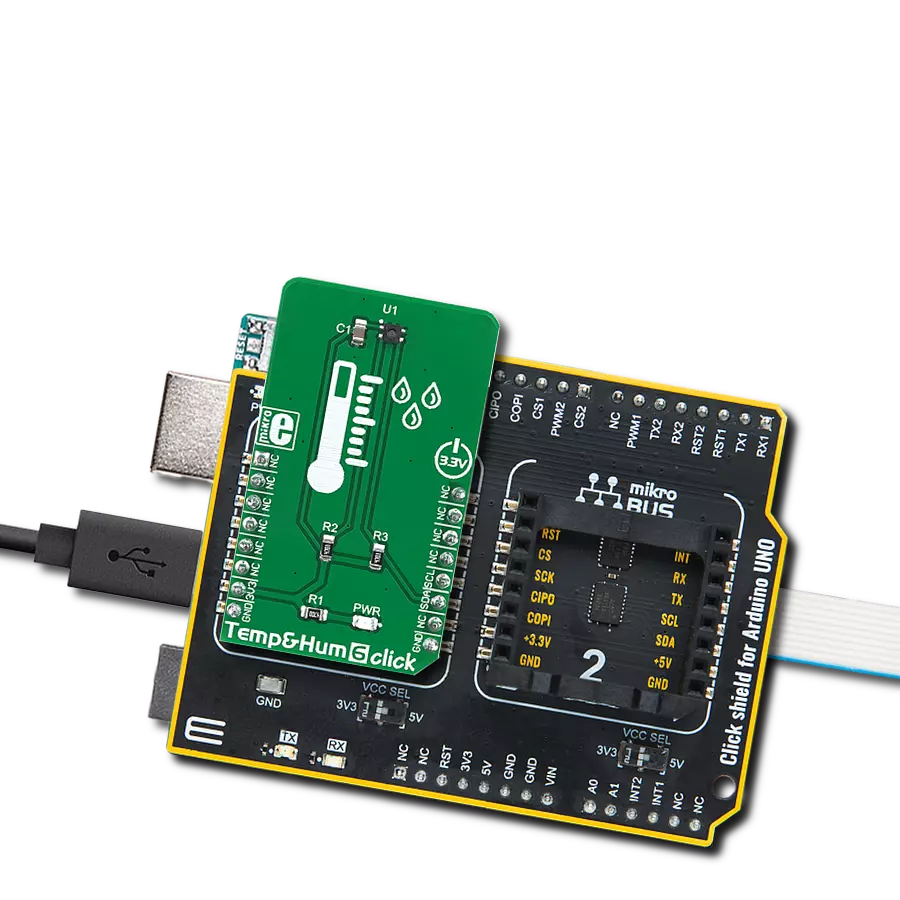
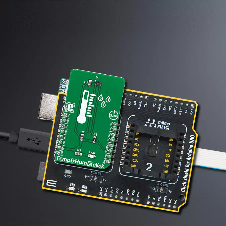
Temp&Hum 6 Click
Dev. board
Arduino UNO Rev3
Compiler
NECTO Studio
MCU
ATmega328P
We help you measure, manage, and master your environment, ensuring that your surroundings are in harmony with your needs and goals
A
A
Hardware Overview
How does it work?
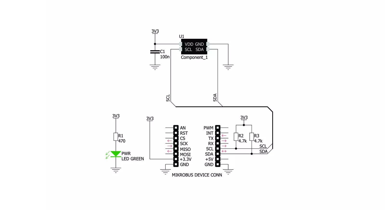
Temp&Hum 6 Click is bsaed on the ENS210, a relative humidity and temperature sensor with I²C Interface, from ScioSense. This sensor IC integrates two very accurate sensing components: temperature sensor, and relative humidity sensor. Thanks to an integrated logic back-end section, the IC can output calibrated readings from both sensors in human-readable format (%RH, and K). The ENS210 incorporates a high accuracy thermal sensor, which can measure the temperature in the range between -40°C and 100°C while retaining accuracy of ±0.5°C. The accuracy is even greater if the range is narrowed down: when used over the range between 0°C and 70°C, the typical accuracy is ±0.2°C. Also, the repeatability of the temperature measurement is very good, in the range of ±0.1°C. The ENS210 is very reliable. It can be used for prolonged periods of time, as it has a very low thermal drift of only 0.005°C per year. After the measurement has been converted by the A/D converter which uses a relatively new hybrid-mode
technology (Zoom ADC), it is fed to a logic back-end, which applies factory-calibrated correction, and converts the raw data into Kelvins. Note that the sensor will take some time to accommodate to the ambient temperature, especially if the temperature changes quickly, considering the thermal conductivity of the PCB itself. However, the Click board™ surface is not very large, resulting in lower thermal inertia. The humidity sensor is a capacitor-based sensor, which consists of a humidity-sensitive large-area capacitor. The humidity-sensitive layer allows the capacitance changes proportional to relative humidity. The capacitance has a linear dependence on temperature, which ensures high accuracy. However, the accuracy of the relative humidity sensor changes with the ambient temperature, as well as with the %RH. The datasheet of the ENS210 offers an absolute accuracy map, covering a range of different %RH and °C values. The RH sensor accuracy varies in the range between ±2.5% and ±5.5%, depending on the
measuring conditions. This table can be used to check the exact accuracy for some specific conditions. After the measurement has been converted by a high-precision 2nd order sigma-delta ADC, the logic back-end section applies the factory-calibrated correction and converts the raw data into %RH value. Note that the capacitor-based humidity sensors commonly suffer from a small hysteresis that might occur if the sensor is used in very humid conditions for prolonged periods of time. However, this hysteresis is not irreversible. The ENS210 does not exhibit a significant hysteresis effect. The datasheet specifies it to be ±0.7 %RH in the range between 20% to 90% RH, and ambient temperature of 25 °C. Temp&Hum 6 click uses the I2C communication interface. It has pull-up resistors connected to the mikroBUS™ 3.3V rail. A proper conversion of logic voltage levels should be applied before the Click board™ is used with MCUs operated with 5V.

Features overview
Development board
Arduino UNO is a versatile microcontroller board built around the ATmega328P chip. It offers extensive connectivity options for various projects, featuring 14 digital input/output pins, six of which are PWM-capable, along with six analog inputs. Its core components include a 16MHz ceramic resonator, a USB connection, a power jack, an
ICSP header, and a reset button, providing everything necessary to power and program the board. The Uno is ready to go, whether connected to a computer via USB or powered by an AC-to-DC adapter or battery. As the first USB Arduino board, it serves as the benchmark for the Arduino platform, with "Uno" symbolizing its status as the
first in a series. This name choice, meaning "one" in Italian, commemorates the launch of Arduino Software (IDE) 1.0. Initially introduced alongside version 1.0 of the Arduino Software (IDE), the Uno has since become the foundational model for subsequent Arduino releases, embodying the platform's evolution.

Microcontroller Overview
MCU Card / MCU

Architecture
AVR
MCU Memory (KB)
32
Silicon Vendor
Microchip
Pin count
28
RAM (Bytes)
2048
You complete me!
Accessories
Click Shield for Arduino UNO has two proprietary mikroBUS™ sockets, allowing all the Click board™ devices to be interfaced with the Arduino UNO board without effort. The Arduino Uno, a microcontroller board based on the ATmega328P, provides an affordable and flexible way for users to try out new concepts and build prototypes with the ATmega328P microcontroller from various combinations of performance, power consumption, and features. The Arduino Uno has 14 digital input/output pins (of which six can be used as PWM outputs), six analog inputs, a 16 MHz ceramic resonator (CSTCE16M0V53-R0), a USB connection, a power jack, an ICSP header, and reset button. Most of the ATmega328P microcontroller pins are brought to the IO pins on the left and right edge of the board, which are then connected to two existing mikroBUS™ sockets. This Click Shield also has several switches that perform functions such as selecting the logic levels of analog signals on mikroBUS™ sockets and selecting logic voltage levels of the mikroBUS™ sockets themselves. Besides, the user is offered the possibility of using any Click board™ with the help of existing bidirectional level-shifting voltage translators, regardless of whether the Click board™ operates at a 3.3V or 5V logic voltage level. Once you connect the Arduino UNO board with our Click Shield for Arduino UNO, you can access hundreds of Click boards™, working with 3.3V or 5V logic voltage levels.

Used MCU Pins
mikroBUS™ mapper
Take a closer look
Click board™ Schematic
Step by step
Project assembly

Start by selecting your development board and Click board™. Begin with the Arduino UNO Rev3 as your development board.


Track your results in real time
Application Output
1. Application Output - In Debug mode, the 'Application Output' window enables real-time data monitoring, offering direct insight into execution results. Ensure proper data display by configuring the environment correctly using the provided tutorial.

2. UART Terminal - Use the UART Terminal to monitor data transmission via a USB to UART converter, allowing direct communication between the Click board™ and your development system. Configure the baud rate and other serial settings according to your project's requirements to ensure proper functionality. For step-by-step setup instructions, refer to the provided tutorial.

3. Plot Output - The Plot feature offers a powerful way to visualize real-time sensor data, enabling trend analysis, debugging, and comparison of multiple data points. To set it up correctly, follow the provided tutorial, which includes a step-by-step example of using the Plot feature to display Click board™ readings. To use the Plot feature in your code, use the function: plot(*insert_graph_name*, variable_name);. This is a general format, and it is up to the user to replace 'insert_graph_name' with the actual graph name and 'variable_name' with the parameter to be displayed.

Software Support
Library Description
This library contains API for Temp&Hum 6 Click driver.
Key functions:
temphum6_read_temperature- This function returns read Temperature data.temphum6_read_relative_huminidy- This function returns read relative Humidity data.temphum6_get_part_id- This function returns the device part id.
Open Source
Code example
The complete application code and a ready-to-use project are available through the NECTO Studio Package Manager for direct installation in the NECTO Studio. The application code can also be found on the MIKROE GitHub account.
/*!
 * \file
 * \brief TempHum6 Click example
 *
 * # Description
 * This application emasures temperature and humidity.
 *
 * The demo application is composed of two sections :
 *
 * ## Application Init
 * Initialization driver init and reset device and read Part ID
 *
 * ## Application Task
 * Reads Temperature and Huminidy data and logs this data to USBUART every 1sec.
 *
 *
 * \author MikroE Team
 *
 */
// ------------------------------------------------------------------- INCLUDES

#include "board.h"
#include "log.h"
#include "temphum6.h"

// ------------------------------------------------------------------ VARIABLES

static temphum6_t temphum6;
static log_t logger;

// ------------------------------------------------------ APPLICATION FUNCTIONS

void application_init ( void )
{
    log_cfg_t log_cfg;
    temphum6_cfg_t cfg;
    uint16_t part_id;

    /**
     * Logger initialization.
     * Default baud rate: 115200
     * Default log level: LOG_LEVEL_DEBUG
     * @note If USB_UART_RX and USB_UART_TX
     * are defined as HAL_PIN_NC, you will
     * need to define them manually for log to work.
     * See @b LOG_MAP_USB_UART macro definition for detailed explanation.
     */
    LOG_MAP_USB_UART( log_cfg );
    log_init( &logger, &log_cfg );
    log_info( &logger, "---- Application Init ----" );

    //  Click initialization.

    temphum6_cfg_setup( &cfg );
    TEMPHUM6_MAP_MIKROBUS( cfg, MIKROBUS_1 );
    temphum6_init( &temphum6, &cfg );

    temphum6_reset( &temphum6 );

    part_id = temphum6_get_part_id( &temphum6 );
    if ( part_id == TEMPHUM6_PART_ID )
    {
        log_printf( &logger, "Device OK - read ID is OK  0x%x\r\n", part_id );
    }
    else
    {
        log_printf( &logger, "Device ERROR - read ID is NOT OK 0x%x\r\n", part_id  );
        for ( ; ; );
    }
}

void application_task ( void )
{
    //  Task implementation.

    float temp;
    float hum;

    temp = temphum6_read_temperature( &temphum6, TEMPHUM6_TEMP_IN_CELSIUS );
    log_printf( &logger, "Temperature is %.2f C\r\n", temp );

    hum = temphum6_read_relative_huminidy( &temphum6 );
    log_printf( &logger, "Huminidy is %.2f %%RH\r\n", hum );

    log_printf( &logger, "------------------\r\n");
    Delay_ms ( 1000 );
}

int main ( void )
{
    /* Do not remove this line or clock might not be set correctly. */
    #ifdef PREINIT_SUPPORTED
    preinit();
    #endif

    application_init( );

    for ( ; ; )
    {
        application_task( );
    }

    return 0;
}

// ------------------------------------------------------------------------ END
Additional Support
Resources
Category:Temperature & humidity


