Implement advanced motion tracking in your future projects using IAM-20680 and STM32F091RC
Mastering 3D space: Total sotion control
Published Feb 26, 2024
Click board™
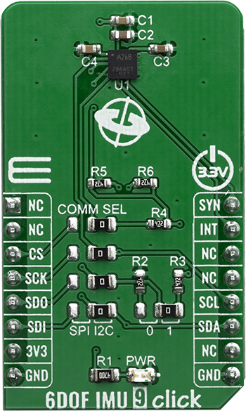
6DOF IMU 9 Click
Dev. board
Nucleo-64 with STM32F091RC MCU
Compiler
NECTO Studio
MCU
STM32F091RC
Enable intuitive gesture controls across devices, allowing actions such as scrolling, selecting, and adjusting settings with natural hand movements
A
A
Hardware Overview
How does it work?
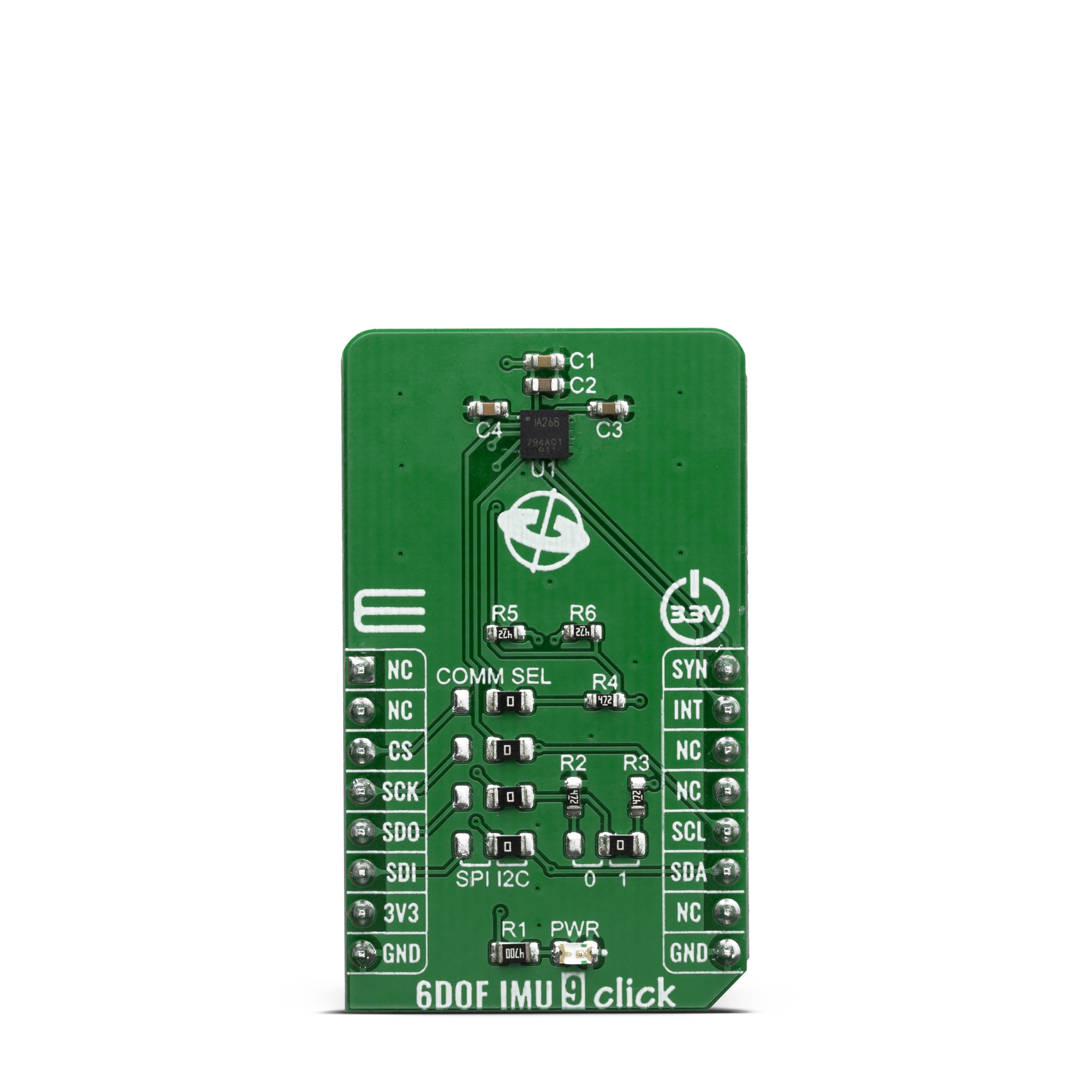
6DOF IMU 9 Click is based on the IAM-20680, a 6-axis MotionTracking device for Automotive applications from TDK that combines a 3-axis gyroscope and a 3-axis accelerometer in a small 3x3x0.75mm (16-pin LGA) package. It also features a 512- byte FIFO that can lower the traffic on the serial bus interface and reduce power consumption by allowing the system processor to burst read sensor data and then go into a low-power mode. IAM-20680, with its 6-axis integration, enables manufacturers to eliminate the costly and complex selection, qualification, and system level integration of discrete devices, guaranteeing optimal motion performance. The IAM-20680 has many features including the Digital-output X-, Y-, and Z-axis angular rate sensors (gyroscopes) with a user-programmable full-scale range of ±250 dps, ±500 dps, ±1000 dps, and ±2000 dps and integrated 16-bit ADCs, Digital-output X-, Y-, and Z-axis accelerometer with a programmable full scale range of ±2g, ±4g, ±8g,
and ±16g and integrated 16-bit ADCs and a User-programmable digital filters for gyroscope, accelerometer, and temperature sensor. The IAM-20680 includes the following additional features such as minimal cross-axis sensitivity between the accelerometer and gyroscope axes, a 512-byte FIFO buffer enables the applications processor to read the data in bursts, with a digital-output temperature sensor and the MEMS structure hermetically sealed and bonded at wafer level. The 6DOF IMU 9 communicates to a system processor using either a SPI or an I2C serial interface. The IAM-20680 contains a 512-byte FIFO register that is accessible via the Serial Interface. The FIFO configuration register determines which data are written into the FIFO. Possible choices include gyro data, accelerometer data, temperature readings, and FSYNC input. A FIFO counter keeps track of how many bytes of valid data are contained in the FIFO. The FIFO register supports burst reads. The interrupt function may be used to
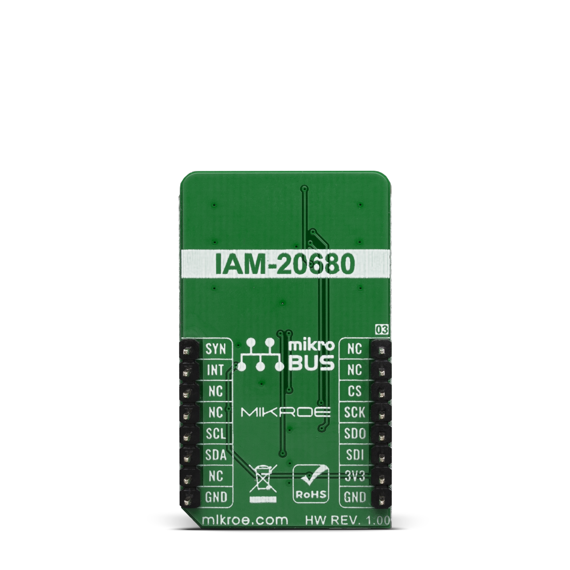
determine when new data are available. The IAM-20680 allows FIFO read in low-power accelerometer mode. 6DOF IMU 9 click supports both SPI and I2C communication interfaces, allowing it to be used with a wide range of different MCUs. The communication interface can be selected by moving SMD jumpers grouped under the COM SEL to an appropriate position (SPI or I2C). The slave I2C address can also be configured by an SMD jumper when the Click board™ is operated in the I2C mode an SMD jumper labeled as ADD LSB is used to set the least significant bit (LSB) of the I2C address. Due to the IAM-20680, the 6DOF IMU 9 click can be used for automotive applications and navigation systems aids for dead reckoning, lift gate motion detection, accurate location for vehicle to vehicle and infrastructure, 360º view camera stabilization, car alarm, telematics and insurance vehicle tracking.
Features overview
Development board
Nucleo-64 with STM32F091RC MCU offers a cost-effective and adaptable platform for developers to explore new ideas and prototype their designs. This board harnesses the versatility of the STM32 microcontroller, enabling users to select the optimal balance of performance and power consumption for their projects. It accommodates the STM32 microcontroller in the LQFP64 package and includes essential components such as a user LED, which doubles as an ARDUINO® signal, alongside user and reset push-buttons, and a 32.768kHz crystal oscillator for precise timing operations. Designed with expansion and flexibility in mind, the Nucleo-64 board features an ARDUINO® Uno V3 expansion connector and ST morpho extension pin
headers, granting complete access to the STM32's I/Os for comprehensive project integration. Power supply options are adaptable, supporting ST-LINK USB VBUS or external power sources, ensuring adaptability in various development environments. The board also has an on-board ST-LINK debugger/programmer with USB re-enumeration capability, simplifying the programming and debugging process. Moreover, the board is designed to simplify advanced development with its external SMPS for efficient Vcore logic supply, support for USB Device full speed or USB SNK/UFP full speed, and built-in cryptographic features, enhancing both the power efficiency and security of projects. Additional connectivity is
provided through dedicated connectors for external SMPS experimentation, a USB connector for the ST-LINK, and a MIPI® debug connector, expanding the possibilities for hardware interfacing and experimentation. Developers will find extensive support through comprehensive free software libraries and examples, courtesy of the STM32Cube MCU Package. This, combined with compatibility with a wide array of Integrated Development Environments (IDEs), including IAR Embedded Workbench®, MDK-ARM, and STM32CubeIDE, ensures a smooth and efficient development experience, allowing users to fully leverage the capabilities of the Nucleo-64 board in their projects.

Microcontroller Overview
MCU Card / MCU

Architecture
ARM Cortex-M0
MCU Memory (KB)
256
Silicon Vendor
STMicroelectronics
Pin count
64
RAM (Bytes)
32768
You complete me!
Accessories
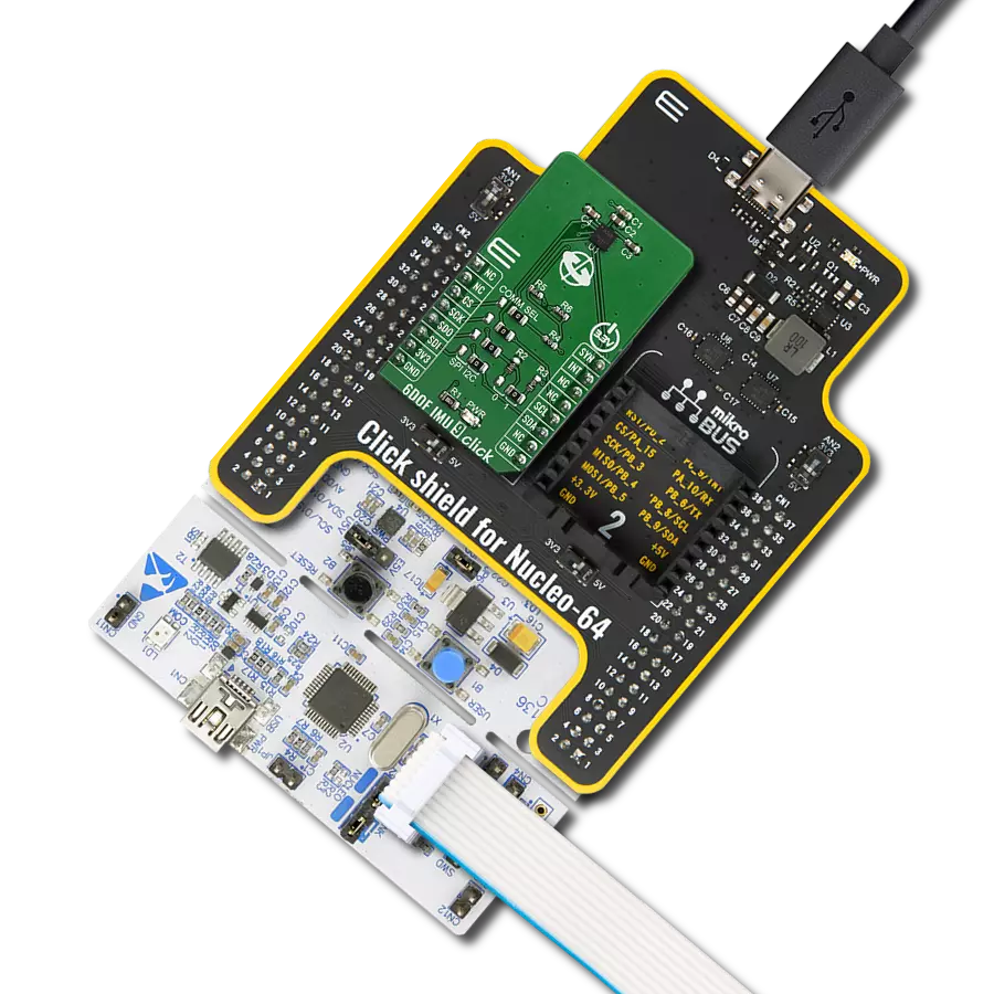
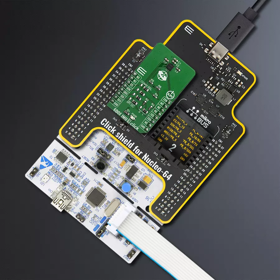
Click Shield for Nucleo-64 comes equipped with two proprietary mikroBUS™ sockets, allowing all the Click board™ devices to be interfaced with the STM32 Nucleo-64 board with no effort. This way, Mikroe allows its users to add any functionality from our ever-growing range of Click boards™, such as WiFi, GSM, GPS, Bluetooth, ZigBee, environmental sensors, LEDs, speech recognition, motor control, movement sensors, and many more. More than 1537 Click boards™, which can be stacked and integrated, are at your disposal. The STM32 Nucleo-64 boards are based on the microcontrollers in 64-pin packages, a 32-bit MCU with an ARM Cortex M4 processor operating at 84MHz, 512Kb Flash, and 96KB SRAM, divided into two regions where the top section represents the ST-Link/V2 debugger and programmer while the bottom section of the board is an actual development board. These boards are controlled and powered conveniently through a USB connection to program and efficiently debug the Nucleo-64 board out of the box, with an additional USB cable connected to the USB mini port on the board. Most of the STM32 microcontroller pins are brought to the IO pins on the left and right edge of the board, which are then connected to two existing mikroBUS™ sockets. This Click Shield also has several switches that perform functions such as selecting the logic levels of analog signals on mikroBUS™ sockets and selecting logic voltage levels of the mikroBUS™ sockets themselves. Besides, the user is offered the possibility of using any Click board™ with the help of existing bidirectional level-shifting voltage translators, regardless of whether the Click board™ operates at a 3.3V or 5V logic voltage level. Once you connect the STM32 Nucleo-64 board with our Click Shield for Nucleo-64, you can access hundreds of Click boards™, working with 3.3V or 5V logic voltage levels.

Used MCU Pins
mikroBUS™ mapper
Take a closer look
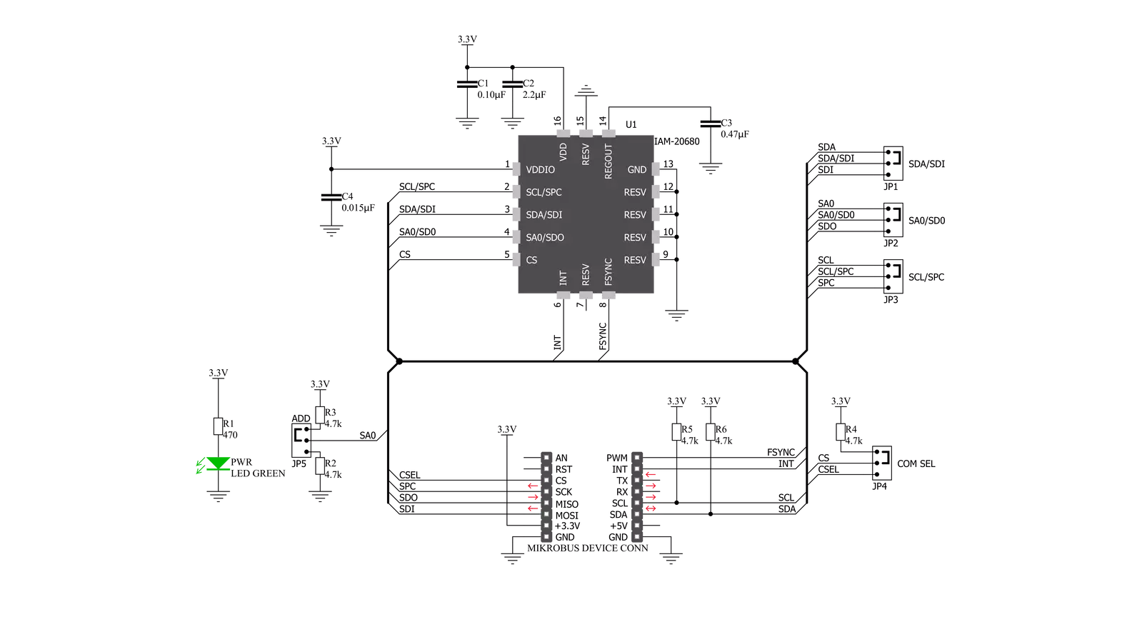
Click board™ Schematic
Step by step
Project assembly
Start by selecting your development board and Click board™. Begin with the Nucleo-64 with STM32F091RC MCU as your development board.


Software Support
Library Description
This library contains API for 6DOF IMU 9 Click driver.
Key functions:
c6dofimu9_set_gyro_config- Set Gyro configuration functionc6dofimu9_set_gyro_measurement_range- Set Gyro measurement range configuration functionc6dofimu9_set_accel_measurement_range- Set Accel measurement range configuration function
Open Source
Code example
The complete application code and a ready-to-use project are available through the NECTO Studio Package Manager for direct installation in the NECTO Studio. The application code can also be found on the MIKROE GitHub account.
/*!
 * \file
 * \brief 6DOFIMU9 Click example
 *
 * # Description
 * This application measure 3-axis gyroscope and a 3-axis accelerometer.
 *
 * The demo application is composed of two sections :
 *
 * ## Application Init
 * Initialization driver enables - I2C, check device ID,
 * configure accelerometer and gyroscope, also write log.
 *
 * ## Application Task
 * This is an example which demonstrates the use of 6DOF IMU 9 Click board.
 * Measured and display Accel and Gyro data coordinates values for X-axis, Y-axis and Z-axis.
 * Results are being sent to the Usart Terminal where you can track their changes.
 * All data logs write on USB uart changes for every 1 sec.
 *
 * \author MikroE Team
 *
 */
// ------------------------------------------------------------------- INCLUDES

#include "board.h"
#include "log.h"
#include "c6dofimu9.h"

// ------------------------------------------------------------------ VARIABLES

static c6dofimu9_t c6dofimu9;
static log_t logger;

// ------------------------------------------------------ APPLICATION FUNCTIONS

void application_init ( void )
{
    log_cfg_t log_cfg;
    c6dofimu9_cfg_t cfg;
    uint8_t device_id;

    /**
     * Logger initialization.
     * Default baud rate: 115200
     * Default log level: LOG_LEVEL_DEBUG
     * @note If USB_UART_RX and USB_UART_TX
     * are defined as HAL_PIN_NC, you will
     * need to define them manually for log to work.
     * See @b LOG_MAP_USB_UART macro definition for detailed explanation.
     */
    LOG_MAP_USB_UART( log_cfg );
    log_init( &logger, &log_cfg );
    log_info( &logger, "---- Application Init ----" );

    //  Click initialization.

    c6dofimu9_cfg_setup( &cfg );
    C6DOFIMU9_MAP_MIKROBUS( cfg, MIKROBUS_1 );
    c6dofimu9_init( &c6dofimu9, &cfg );

    log_printf( &logger, "       Driver  Initialization        \r\n" );
    log_printf( &logger, "-------------------------------------\r\n" );
    Delay_ms ( 100 );

    device_id = c6dofimu9_get_device_id( &c6dofimu9 );

    if ( device_id == C6DOFIMU9_DEVICE_ID )
    {
        log_printf( &logger, "       SUCCESS        \r\n" );
        log_printf( &logger, "-------------------------------------\r\n" );
    }
    else
    {
        log_printf( &logger, "                ERROR              \r\n" );
        log_printf( &logger, "            RESET DEVICE           \r\n" );
        log_printf( &logger, "-----------------------------------\r\n" );
        for ( ; ; );
    }

    c6dofimu9_set_gyro_config_lp_mode( &c6dofimu9, C6DOFIMU9_GYRO_AVERAGE_1x );
    c6dofimu9_set_gyro_measurement_range( &c6dofimu9, C6DOFIMU9_GYRO_FULL_SCALE_250dps );
    c6dofimu9_set_accel_measurement_range( &c6dofimu9, C6DOFIMU9_ACCEL_FULL_SCALE_2g );
    c6dofimu9_set_accel_avg_filter_mode( &c6dofimu9, C6DOFIMU9_ACCEL_AVERAGE_4_SAMPLES );

    log_printf( &logger, "            Start measurement             \r\n" );
    log_printf( &logger, "-------------------------------------\r\n" );
    Delay_ms ( 100 );
}

void application_task ( )
{
    int16_t accel_axis_x;
    int16_t accel_axis_y;
    int16_t accel_axis_z;
    int16_t gyro_axis_x;
    int16_t gyro_axis_y;
    int16_t gyro_axis_z;

    c6dofimu9_get_accel_data( &c6dofimu9, &accel_axis_x, &accel_axis_y, &accel_axis_z );
    Delay_ms ( 10 );
    c6dofimu9_get_gyro_data( &c6dofimu9, &gyro_axis_x,  &gyro_axis_y, &gyro_axis_z );
    Delay_ms ( 10 );

    log_printf( &logger, " Accel X : %d ", accel_axis_x );
    log_printf( &logger, "    |     ");
    log_printf( &logger, " Gyro X : %d \r\n", gyro_axis_x );

    log_printf( &logger, " Accel Y : %d ", accel_axis_y );
    log_printf( &logger, "    |     ");
    log_printf( &logger, " Gyro Y : %d \r\n", gyro_axis_y );

    log_printf( &logger, " Accel Z : %d ", accel_axis_z );
    log_printf( &logger, "    |     ");
    log_printf( &logger, " Gyro Z : %d \r\n", gyro_axis_z );

    log_printf( &logger, "-------------------------------------\r\n" );
    Delay_ms ( 1000 );
}

int main ( void )
{
    /* Do not remove this line or clock might not be set correctly. */
    #ifdef PREINIT_SUPPORTED
    preinit();
    #endif

    application_init( );

    for ( ; ; )
    {
        application_task( );
    }

    return 0;
}

// ------------------------------------------------------------------------ END
Additional Support
Resources
Category:Motion


