Turn your moves into tangible achievements with with LIS2DW12 and STM32F091RC
Tri-Axis brilliance: Redefining motion tracking for the future

Published Feb 26, 2024
Click board™
Accel 10 Click
Dev. board
Nucleo-64 with STM32F091RC MCU
Compiler
NECTO Studio
MCU
STM32F091RC
Our three-axis accelerometer is engineered to revolutionize motion sensing, providing accurate and real-time measurements for a multitude of applications
A
A
Hardware Overview
How does it work?
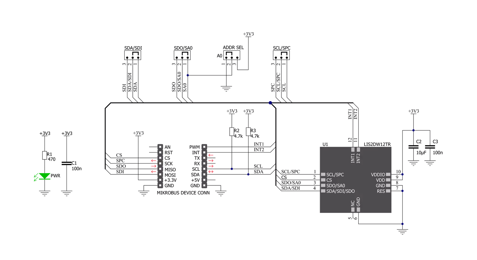
Accel 10 Click is based on the LIS2DW12TR, a high-performance ultra-low-power 3-axis "femto" accelerometer, from STMicroelectronics. This sensor has many features perfectly suited for wearables, handheld, and IoT applications, offering a good balance between the performance and the power consumption. One of its key features is its extremely low power consumption, which makes it perfectly suited for such applications. There are several power modes which the LIS2DW12TR device can use. While in Low Power mode, the device consumes only 0.38µA, but the access to some features is restricted. Having that in mind, accel 10 Click can be used for a rapid development and testing of various applications based on step counting, fitness applications, profile switching and display ON/OFF applications, angle measurement applications, and similar applications. More information can be found within the LIS2DW12TR datasheet. The LIS2DW12TR sensor can measure acceleration within ranges of ±2 g, ±4 g, ±8, and ±16 g. It can output the measurement data using the Output Data Rate (ODR) from 1.6Hz (Low Power mode), up to 1600Hz (Performance mode). A high-precision analog front end facilitates highly sensitive MEMS,
featuring a 14-bit A/D Converter. It allows very high accuracy of the output, even during very low amplitude changes. This makes the sensor particularly sensitive and accurate with movements that generate relatively low acceleration signals. However, using a highly sensitive MEMS makes the LIS2DW12TR prone to damage caused by extremely high g-forces (10,000 g for less than 200 µs). Acceleration data is available in 14-bit format from both the data registers and the internal FIFO buffer, which can can memorize 32 slots of X, Y and Z data. The FIFO buffer can be used for more complex calculations or timed readings, reducing the traffic on the communication interface. FIFO buffer allows optimization within the firmware that runs on the host MCU. Besides the acceleration MEMS and complementary analog front-end circuit, the LIS2DW12TR sensor also has an integrated temperature sensor. It is updated up to 25 times per second, and sampled to an 12-bit value (complement of 2’s format). Interrupts can be triggered for many different events. Some basic events include the data-ready interrupt event and aforementioned FIFO events, while so-called feature engines can trigger an interrupt for any of
the detected motion/movement events, including step detection/counter, activity recognition, tilt on wrist, tap/double tap, any/no motion, and error event interrupt. The extensive interrupt engine can use two programmable interrupt pins. Both of these pins can be assigned with any interrupt source and can be either LOW or HIGH on interrupt, depending on settings in appropriate registers. These two pins are routed to PWM and INT pin of the mikroBUS™, and are labeled as IT1 and IT2, respectively. Accel 10 Click offers two communication interfaces. It can be used with either I2C or SPI. The onboard SMD jumpers labeled as COMM SEL allow switching between the two interfaces. Note that all the jumpers have to be positioned either I2C or to SPI position. When I2C interface is selected, an additional SMD jumper labeled as ADDR SEL becomes available, determining the least significant bit of the LIS2DW12TR I2C address. This Click Board™ uses both I2C and SPI communication interfaces. It is designed to be operated only with 3.3V logic levels. A proper logic voltage level conversion should be performed before the Click board™ is used with MCUs with logic levels of 5V.


Features overview
Development board
Nucleo-64 with STM32F091RC MCU offers a cost-effective and adaptable platform for developers to explore new ideas and prototype their designs. This board harnesses the versatility of the STM32 microcontroller, enabling users to select the optimal balance of performance and power consumption for their projects. It accommodates the STM32 microcontroller in the LQFP64 package and includes essential components such as a user LED, which doubles as an ARDUINO® signal, alongside user and reset push-buttons, and a 32.768kHz crystal oscillator for precise timing operations. Designed with expansion and flexibility in mind, the Nucleo-64 board features an ARDUINO® Uno V3 expansion connector and ST morpho extension pin
headers, granting complete access to the STM32's I/Os for comprehensive project integration. Power supply options are adaptable, supporting ST-LINK USB VBUS or external power sources, ensuring adaptability in various development environments. The board also has an on-board ST-LINK debugger/programmer with USB re-enumeration capability, simplifying the programming and debugging process. Moreover, the board is designed to simplify advanced development with its external SMPS for efficient Vcore logic supply, support for USB Device full speed or USB SNK/UFP full speed, and built-in cryptographic features, enhancing both the power efficiency and security of projects. Additional connectivity is
provided through dedicated connectors for external SMPS experimentation, a USB connector for the ST-LINK, and a MIPI® debug connector, expanding the possibilities for hardware interfacing and experimentation. Developers will find extensive support through comprehensive free software libraries and examples, courtesy of the STM32Cube MCU Package. This, combined with compatibility with a wide array of Integrated Development Environments (IDEs), including IAR Embedded Workbench®, MDK-ARM, and STM32CubeIDE, ensures a smooth and efficient development experience, allowing users to fully leverage the capabilities of the Nucleo-64 board in their projects.

Microcontroller Overview
MCU Card / MCU

Architecture
ARM Cortex-M0
MCU Memory (KB)
256
Silicon Vendor
STMicroelectronics
Pin count
64
RAM (Bytes)
32768
You complete me!
Accessories
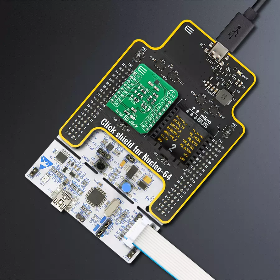
Click Shield for Nucleo-64 comes equipped with two proprietary mikroBUS™ sockets, allowing all the Click board™ devices to be interfaced with the STM32 Nucleo-64 board with no effort. This way, Mikroe allows its users to add any functionality from our ever-growing range of Click boards™, such as WiFi, GSM, GPS, Bluetooth, ZigBee, environmental sensors, LEDs, speech recognition, motor control, movement sensors, and many more. More than 1537 Click boards™, which can be stacked and integrated, are at your disposal. The STM32 Nucleo-64 boards are based on the microcontrollers in 64-pin packages, a 32-bit MCU with an ARM Cortex M4 processor operating at 84MHz, 512Kb Flash, and 96KB SRAM, divided into two regions where the top section represents the ST-Link/V2 debugger and programmer while the bottom section of the board is an actual development board. These boards are controlled and powered conveniently through a USB connection to program and efficiently debug the Nucleo-64 board out of the box, with an additional USB cable connected to the USB mini port on the board. Most of the STM32 microcontroller pins are brought to the IO pins on the left and right edge of the board, which are then connected to two existing mikroBUS™ sockets. This Click Shield also has several switches that perform functions such as selecting the logic levels of analog signals on mikroBUS™ sockets and selecting logic voltage levels of the mikroBUS™ sockets themselves. Besides, the user is offered the possibility of using any Click board™ with the help of existing bidirectional level-shifting voltage translators, regardless of whether the Click board™ operates at a 3.3V or 5V logic voltage level. Once you connect the STM32 Nucleo-64 board with our Click Shield for Nucleo-64, you can access hundreds of Click boards™, working with 3.3V or 5V logic voltage levels.

Used MCU Pins
mikroBUS™ mapper
Take a closer look
Click board™ Schematic
Step by step
Project assembly
Start by selecting your development board and Click board™. Begin with the Nucleo-64 with STM32F091RC MCU as your development board.


Software Support
Library Description
This library contains API for Accel 10 Click driver.
Key functions:
accel10_check_data_ready- Check data ready functionaccel10_get_data- Read Accel data functionaccel10_read_temperature- Read temperature function
Open Source
Code example
The complete application code and a ready-to-use project are available through the NECTO Studio Package Manager for direct installation in the NECTO Studio. The application code can also be found on the MIKROE GitHub account.
/*!
 * \file
 * \brief Accel10 Click example
 *
 * # Description
 * This example demonstrates the use of Accel 10 Click board.
 *
 * The demo application is composed of two sections :
 *
 * ## Application Init
 * Initializes the driver and checks the communication by reading the device ID.
 * After that, performs the Click default configuration.
 *
 * ## Application Task
 * Reads the accel values for X, Y, and Z axis and also reads the temperature in Celsius
 * and displays the results on the USB UART each second.
 *
 * \author Nenad Filipovic
 *
 */
// ------------------------------------------------------------------- INCLUDES

#include "board.h"
#include "log.h"
#include "accel10.h"

// ------------------------------------------------------------------ VARIABLES

static accel10_t accel10;
static log_t logger;

static accel10_data_t accel_data;
static int8_t temperature;

// ------------------------------------------------------ APPLICATION FUNCTIONS

void application_init ( void )
{
    log_cfg_t log_cfg;
    accel10_cfg_t cfg;

    /**
     * Logger initialization.
     * Default baud rate: 115200
     * Default log level: LOG_LEVEL_DEBUG
     * @note If USB_UART_RX and USB_UART_TX
     * are defined as HAL_PIN_NC, you will
     * need to define them manually for log to work.
     * See @b LOG_MAP_USB_UART macro definition for detailed explanation.
     */
    LOG_MAP_USB_UART( log_cfg );
    log_init( &logger, &log_cfg );
    log_info( &logger, "---- Application Init ----" );

    //  Click initialization.

    accel10_cfg_setup( &cfg );
    ACCEL10_MAP_MIKROBUS( cfg, MIKROBUS_1 );
    accel10_init( &accel10, &cfg );
    Delay_ms ( 500 );

    log_printf( &logger, "---------------------\r\n" );
    log_printf( &logger, "    Accel 10 Click\r\n" );
    log_printf( &logger, "---------------------\r\n" );

    // Checking communication
    if ( accel10_check_id( &accel10 ) == ACCEL10_SUCCESS )
    {
        log_printf( &logger, "  Communication  OK\r\n" );
        log_printf( &logger, "---------------------\r\n" );
        Delay_ms ( 100 );
    }
    else
    {
        log_printf( &logger, "  Communication ERROR\r\n" );
        log_printf( &logger, "  Reset the device\r\n" );
        log_printf( &logger, "---------------------\r\n" );
        for ( ; ; );
    }

    accel10_default_cfg ( &accel10 );
    log_printf( &logger, "  Default config.\r\n" );
    log_printf( &logger, "---------------------\r\n" );
    Delay_ms ( 100 );
}

void application_task ( void )
{
    if ( accel10_check_data_ready( &accel10 ) == ACCEL10_STATUS_DATA_READY )
    {
        accel10_get_data ( &accel10, &accel_data );
        Delay_ms ( 10 );

        log_printf( &logger, "  Accel X :  %d\r\n", accel_data.x );
        log_printf( &logger, "  Accel Y :  %d\r\n", accel_data.y );
        log_printf( &logger, "  Accel Z :  %d\r\n", accel_data.z );

        temperature = accel10_read_temperature( &accel10 );
        Delay_ms ( 10 );

        log_printf( &logger, " Temperature :  %d C\r\n", ( int16_t ) temperature );
        log_printf( &logger, "---------------------\r\n" );
        Delay_ms ( 1000 );
    }
}

int main ( void )
{
    /* Do not remove this line or clock might not be set correctly. */
    #ifdef PREINIT_SUPPORTED
    preinit();
    #endif

    application_init( );

    for ( ; ; )
    {
        application_task( );
    }

    return 0;
}


// ------------------------------------------------------------------------ END
Additional Support
Resources
Category:Motion


