Step beyond touch interfaces with gesture-based solution based on ICM-40627 and STM32F446RE
Join the gesture sensing revolution
Published Oct 08, 2024
Click board™
Air Motion Click
Dev. board
Nucleo 64 with STM32F446RE MCU
Compiler
NECTO Studio
MCU
STM32F446RE
From motion to magic, our gesture-based solution ushers in a new era of handheld applications, where your gestures become commands
A
A
Hardware Overview
How does it work?
Air Motion Click is based on the ICM-40627, a 6-axis MotionTracking™ device that combines a 3-axis gyroscope and a 3-axis accelerometer from TDK InvenSense. It features a 2K-byte FIFO that can lower the traffic on the selected serial bus interface and reduce power consumption by allowing the system processor to burst read sensor data and then go into a low-power mode. With its 6-axis integration, the ICM-40627 guarantees optimal motion performance for customers. The ICM-40627 comes bundled with TDK's Air Motion Library that enables precise mouse pointing, swipe, roll, gesture wake-up, and other motion gestures, making this Click board™ a suitable solution for gesture-based handheld applications. The gyroscope supports eight programmable full-scale range settings from ±15.65dps to ±2000dps, and the accelerometer supports four
programmable full-scale range settings from ±2g to ±16g. Other industry-leading features include InvenSense on-chip APEX Motion Processing engine for gesture recognition, activity classification, and pedometer, along with on-chip 16-bit ADCs, programmable digital filters, an embedded temperature sensor, and programmable interrupts. Air Motion Click allows I2C and SPI interfaces at a maximum frequency of 1MHz for I2C and 24MHz for SPI communication. Selection is made by positioning SMD jumpers marked 'COMM SEL' to the appropriate position. Note: All jumpers' positions must be on the same side, or the Click board™ may become unresponsive. When the I2C interface is selected, the ICM-40627 allows the choice of the least significant bit (LSB) of its I2C slave address, using the ADDR SEL SMD jumper set to an appropriate
position marked 0 and 1. The ICM-40627 also has a programmable interrupt system, configured via the Interrupt Configuration register, that can generate an interrupt signal on the INT pins, INT1 and INT2 pins routed on the INT and AN pins of the mikroBUS™ socket. Events like new read-data availability (from the FIFO and Data registers), accelerometer events, FIFO watermark, and overflow can all trigger an interrupt. This Click board™ can be operated only with a 3.3V logic voltage level. The board must perform appropriate logic voltage level conversion before using MCUs with different logic levels. Also, it comes equipped with a library containing functions and an example code that can be used as a reference for further development.


Features overview
Development board
Nucleo-64 with STM32F446RE MCU offers a cost-effective and adaptable platform for developers to explore new ideas and prototype their designs. This board harnesses the versatility of the STM32 microcontroller, enabling users to select the optimal balance of performance and power consumption for their projects. It accommodates the STM32 microcontroller in the LQFP64 package and includes essential components such as a user LED, which doubles as an ARDUINO® signal, alongside user and reset push-buttons, and a 32.768kHz crystal oscillator for precise timing operations. Designed with expansion and flexibility in mind, the Nucleo-64 board features an ARDUINO® Uno V3 expansion connector and ST morpho extension pin
headers, granting complete access to the STM32's I/Os for comprehensive project integration. Power supply options are adaptable, supporting ST-LINK USB VBUS or external power sources, ensuring adaptability in various development environments. The board also has an on-board ST-LINK debugger/programmer with USB re-enumeration capability, simplifying the programming and debugging process. Moreover, the board is designed to simplify advanced development with its external SMPS for efficient Vcore logic supply, support for USB Device full speed or USB SNK/UFP full speed, and built-in cryptographic features, enhancing both the power efficiency and security of projects. Additional connectivity is
provided through dedicated connectors for external SMPS experimentation, a USB connector for the ST-LINK, and a MIPI® debug connector, expanding the possibilities for hardware interfacing and experimentation. Developers will find extensive support through comprehensive free software libraries and examples, courtesy of the STM32Cube MCU Package. This, combined with compatibility with a wide array of Integrated Development Environments (IDEs), including IAR Embedded Workbench®, MDK-ARM, and STM32CubeIDE, ensures a smooth and efficient development experience, allowing users to fully leverage the capabilities of the Nucleo-64 board in their projects.

Microcontroller Overview
MCU Card / MCU

Architecture
ARM Cortex-M4
MCU Memory (KB)
512
Silicon Vendor
STMicroelectronics
Pin count
64
RAM (Bytes)
131072
You complete me!
Accessories
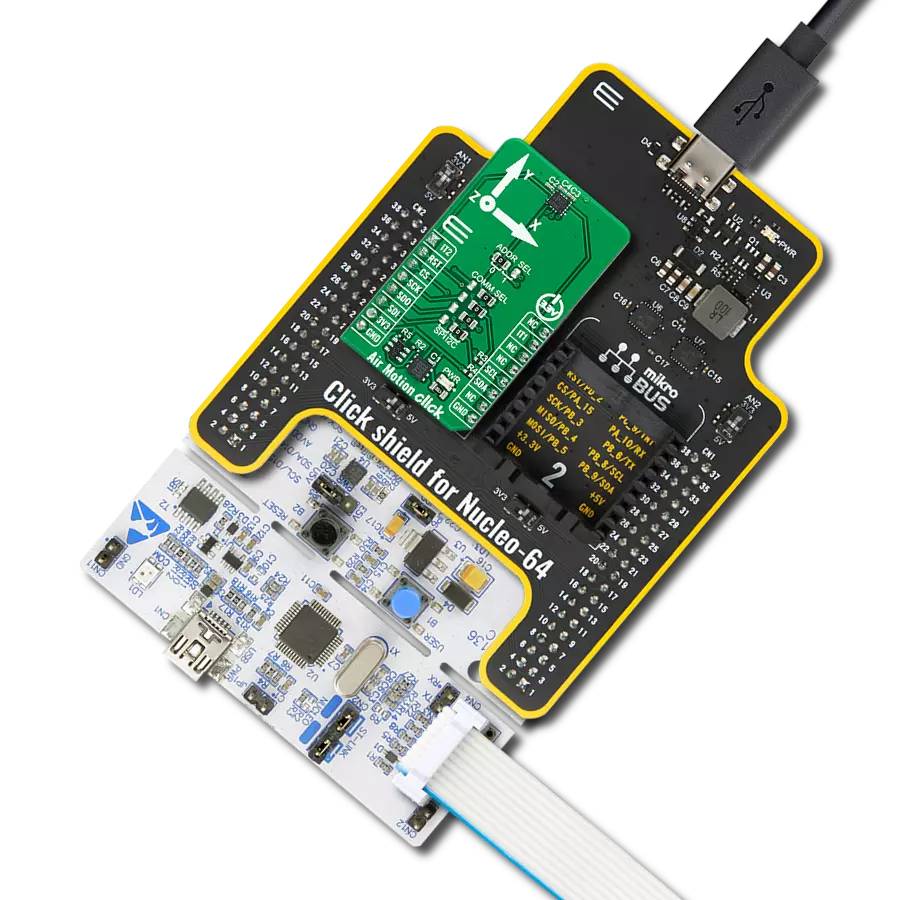
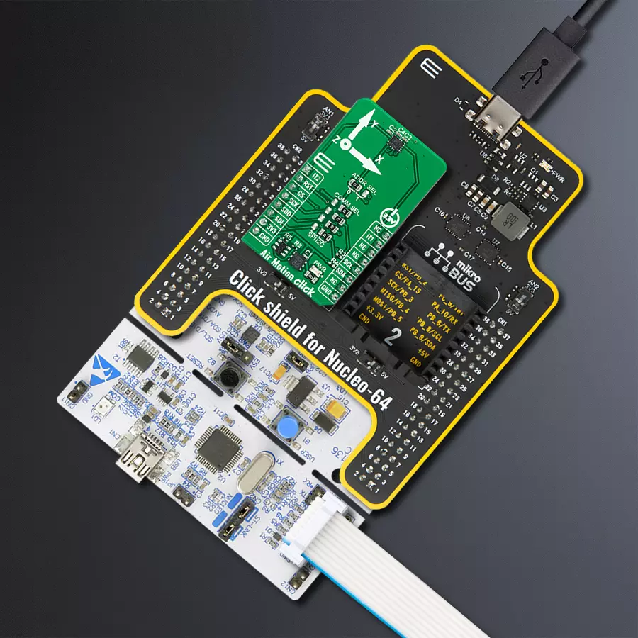
Click Shield for Nucleo-64 comes equipped with two proprietary mikroBUS™ sockets, allowing all the Click board™ devices to be interfaced with the STM32 Nucleo-64 board with no effort. This way, Mikroe allows its users to add any functionality from our ever-growing range of Click boards™, such as WiFi, GSM, GPS, Bluetooth, ZigBee, environmental sensors, LEDs, speech recognition, motor control, movement sensors, and many more. More than 1537 Click boards™, which can be stacked and integrated, are at your disposal. The STM32 Nucleo-64 boards are based on the microcontrollers in 64-pin packages, a 32-bit MCU with an ARM Cortex M4 processor operating at 84MHz, 512Kb Flash, and 96KB SRAM, divided into two regions where the top section represents the ST-Link/V2 debugger and programmer while the bottom section of the board is an actual development board. These boards are controlled and powered conveniently through a USB connection to program and efficiently debug the Nucleo-64 board out of the box, with an additional USB cable connected to the USB mini port on the board. Most of the STM32 microcontroller pins are brought to the IO pins on the left and right edge of the board, which are then connected to two existing mikroBUS™ sockets. This Click Shield also has several switches that perform functions such as selecting the logic levels of analog signals on mikroBUS™ sockets and selecting logic voltage levels of the mikroBUS™ sockets themselves. Besides, the user is offered the possibility of using any Click board™ with the help of existing bidirectional level-shifting voltage translators, regardless of whether the Click board™ operates at a 3.3V or 5V logic voltage level. Once you connect the STM32 Nucleo-64 board with our Click Shield for Nucleo-64, you can access hundreds of Click boards™, working with 3.3V or 5V logic voltage levels.

Used MCU Pins
mikroBUS™ mapper
Take a closer look
Click board™ Schematic

Step by step
Project assembly
Start by selecting your development board and Click board™. Begin with the Nucleo 64 with STM32F446RE MCU as your development board.


Software Support
Library Description
This library contains API for Air Motion Click driver.
Key functions:
airmotion_set_reg_bank- Air Motion set register bank functionairmotion_sw_reset- Air Motion software reset functionairmotion_get_data_from_register- Air Motion read data function
Open Source
Code example
The complete application code and a ready-to-use project are available through the NECTO Studio Package Manager for direct installation in the NECTO Studio. The application code can also be found on the MIKROE GitHub account.
/*!
 * @file main.c
 * @brief Air Motion Click example
 *
 * # Description
 * This example demonstrates the use of Air Motion Click board.
 *
 * The demo application is composed of two sections :
 *
 * ## Application Init
 * Initializes the driver after that resets the device and
 * performs default configuration and reads the device id.
 *
 * ## Application Task
 * When the device is in Tap Detection Mode, Air Motion Click board will read and display the direction,
 * axis, and number of taps that it detected.
 * If Tap Detection mode is disabled, the device will read accel, gyro, and temperature data.
 *
 * @author Stefan Ilic
 *
 */

#include "board.h"
#include "log.h"
#include "airmotion.h"

#define TAP_DETECTION_MODE

static airmotion_t airmotion;
static log_t logger;

void application_init ( void )
{
    log_cfg_t log_cfg;  /**< Logger config object. */
    airmotion_cfg_t airmotion_cfg;  /**< Click config object. */

    /**
     * Logger initialization.
     * Default baud rate: 115200
     * Default log level: LOG_LEVEL_DEBUG
     * @note If USB_UART_RX and USB_UART_TX
     * are defined as HAL_PIN_NC, you will
     * need to define them manually for log to work.
     * See @b LOG_MAP_USB_UART macro definition for detailed explanation.
     */
    LOG_MAP_USB_UART( log_cfg );
    log_init( &logger, &log_cfg );
    log_info( &logger, " Application Init " );

    // Click initialization.
    airmotion_cfg_setup( &airmotion_cfg );
    AIRMOTION_MAP_MIKROBUS( airmotion_cfg, MIKROBUS_1 );
    err_t init_flag = airmotion_init( &airmotion, &airmotion_cfg );
    if ( ( I2C_MASTER_ERROR == init_flag ) || ( SPI_MASTER_ERROR == init_flag ) )
    {
        log_error( &logger, " Communication init." );
        for ( ; ; );
    }

    if ( AIRMOTION_OK != airmotion_default_cfg ( &airmotion ) )
    {
        log_error( &logger, " Default configuration." );
        for ( ; ; );
    }

    log_info( &logger, " Application Task " );

    uint8_t id = 0;
    airmotion_reg_read( &airmotion, AIRMOTION_BANK0_SEL, AIRMOTION_WHO_AM_I, &id, 1);
    log_printf( &logger, " WHO AM I = 0X%.2X\r\n", (uint16_t)id );

#if defined TAP_DETECTION_MODE
    log_printf( &logger, " Tap Detection Mode \r\n" );
    airmotion_set_basic_tap_detection( &airmotion );
#endif

}

void application_task ( void )
{
    if ( airmotion_get_int1_state( &airmotion) )
    {
#if defined TAP_DETECTION_MODE
        uint8_t tap_num;
        uint8_t tap_axis;
        uint8_t tap_dir;

        airmotion_get_tap_detection( &airmotion, &tap_num, &tap_axis, &tap_dir );
        if (  AIRMOTION_TAP_SINGLE == tap_num )
        {
            log_printf( &logger, " SINGLE TAP" );
        }
        else
        {
            log_printf( &logger, " DOUBLE TAP" );
        }

        if (  AIRMOTION_TAP_DIR_POSITIVE == tap_dir )
        {
            log_printf( &logger, " IN POSITIVE" );
        }
        else
        {
            log_printf( &logger, " IN NEGATIVE" );
        }

        if (  AIRMOTION_TAP_AXIS_X == tap_axis )
        {
            log_printf( &logger, " X AXIS DIRECTION \r\n" );
        }
        else if ( AIRMOTION_TAP_AXIS_Y == tap_axis )
        {
            log_printf( &logger, " Y AXIS DIRECTION  \r\n" );
        }
        else
        {
            log_printf( &logger, " Z AXIS DIRECTION  \r\n" );
        }
#else
        airmotion_data_t accel_data;
        airmotion_data_t gyro_data;
        float temp_data;
        uint32_t tmst_data;

        airmotion_get_data_from_register( &airmotion, &temp_data, &accel_data, &gyro_data, &tmst_data );
        log_printf( &logger, " TEMP: %.2f \r\n", temp_data );
        log_printf( &logger, " GYRO: x:%d y:%d z:%d \r\n", gyro_data.data_x,gyro_data.data_y,gyro_data.data_z );
        log_printf( &logger, " ACCEL: x:%d y:%d z:%d \r\n", accel_data.data_x,accel_data.data_y,accel_data.data_z );
        log_printf( &logger, "========================== \r\n" );
        Delay_ms ( 1000 );
#endif
    }
}

int main ( void )
{
    /* Do not remove this line or clock might not be set correctly. */
    #ifdef PREINIT_SUPPORTED
    preinit();
    #endif

    application_init( );

    for ( ; ; )
    {
        application_task( );
    }

    return 0;
}

// ------------------------------------------------------------------------ END
Additional Support
Resources
Category:Motion


