Ensure a captivating sound experience with LM48100Q-Q1 and STM32F031K6
Immerse yourself in the most exquisite musical experiences

Published Oct 01, 2024
Click board™
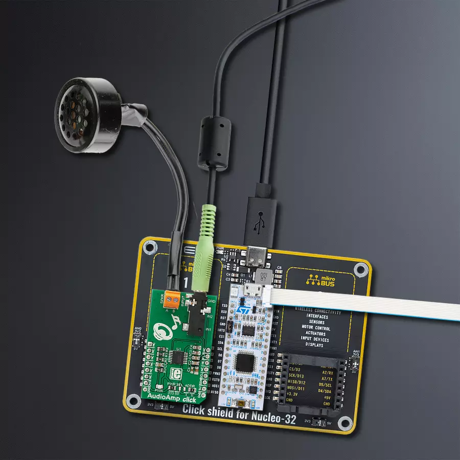
AudioAmp Click
Dev. board
Nucleo 32 with STM32F031K6 MCU
Compiler
NECTO Studio
MCU
STM32F031K6
Don't let poor audio quality hold you back. Add a stereo amplifier to your solution and unlock its full potential
A
A
Hardware Overview
How does it work?
AudioAmp Click is based on the LM48100Q-Q1, a Boomer™ mono, 1.3W audio power amplifier with output fault detection and volume control from Texas Instruments. It has an input mixer and multiplexer, high PSRR, short circuit and thermal protection, advanced click-and-pop suppression, and more. Dual audio input can be mixed/multiplexed to the device output with an independent 32-step volume control. The high power supply rejection ratio (PSRR) allows the device to operate in noisy environments without additional power supply conditioning. In addition, its superior click-and-pop suppression eliminates audible transients on power up/down and during a
shutdown. As mentioned, the LM48100Q-Q1 also features a comprehensive output fault detection system that senses the load conditions, protects the device during short circuit events, and detects open circuit conditions. There are two functional modes for fault diagnostics. In One-Shot mode, after performing the test sequence, enable diagnostic bit is ignored, and the test sequence will not be rerun. In Continuous diagnostic mode, the test sequence is repeated until the device is reset, taken out of this mode, or a fault condition occurs. The AudioAmp Click communicates with the host MCU using the standard I2C 2-Wire interface to read data and configure settings,
supporting a Fast mode operation up to 400KHz. The I2C address can be chosen over the ADDR selection jumper, with 0 selected by default. The fault conditions can be observed via the FLT pin of the mikroBUS™ socket, with a LOW logic state if a fault condition has occurred. This Click board™ can operate with either 3.3V or 5V logic voltage levels selected via the PWR SEL jumper. This way, both 3.3V and 5V capable MCUs can use the communication lines properly. However, the Click board™ comes equipped with a library containing easy-to-use functions and an example code that can be used, as a reference, for further development.

Features overview
Development board
Nucleo 32 with STM32F031K6 MCU board provides an affordable and flexible platform for experimenting with STM32 microcontrollers in 32-pin packages. Featuring Arduino™ Nano connectivity, it allows easy expansion with specialized shields, while being mbed-enabled for seamless integration with online resources. The
board includes an on-board ST-LINK/V2-1 debugger/programmer, supporting USB reenumeration with three interfaces: Virtual Com port, mass storage, and debug port. It offers a flexible power supply through either USB VBUS or an external source. Additionally, it includes three LEDs (LD1 for USB communication, LD2 for power,
and LD3 as a user LED) and a reset push button. The STM32 Nucleo-32 board is supported by various Integrated Development Environments (IDEs) such as IAR™, Keil®, and GCC-based IDEs like AC6 SW4STM32, making it a versatile tool for developers.

Microcontroller Overview
MCU Card / MCU

Architecture
ARM Cortex-M0
MCU Memory (KB)
32
Silicon Vendor
STMicroelectronics
Pin count
32
RAM (Bytes)
4096
You complete me!
Accessories
Click Shield for Nucleo-32 is the perfect way to expand your development board's functionalities with STM32 Nucleo-32 pinout. The Click Shield for Nucleo-32 provides two mikroBUS™ sockets to add any functionality from our ever-growing range of Click boards™. We are fully stocked with everything, from sensors and WiFi transceivers to motor control and audio amplifiers. The Click Shield for Nucleo-32 is compatible with the STM32 Nucleo-32 board, providing an affordable and flexible way for users to try out new ideas and quickly create prototypes with any STM32 microcontrollers, choosing from the various combinations of performance, power consumption, and features. The STM32 Nucleo-32 boards do not require any separate probe as they integrate the ST-LINK/V2-1 debugger/programmer and come with the STM32 comprehensive software HAL library and various packaged software examples. This development platform provides users with an effortless and common way to combine the STM32 Nucleo-32 footprint compatible board with their favorite Click boards™ in their upcoming projects.

Used MCU Pins
mikroBUS™ mapper
Take a closer look
Click board™ Schematic

Step by step
Project assembly

Start by selecting your development board and Click board™. Begin with the Nucleo 32 with STM32F031K6 MCU as your development board.


Software Support
Library Description
This library contains API for AudioAmp Click driver.
Key functions:
audioamp_set_volume- Set mux volume functionaudioamp_set_volume_channel- Set channel volume functionaudioamp_set_normal_operation- Set normal opeation function
Open Source
Code example
The complete application code and a ready-to-use project are available through the NECTO Studio Package Manager for direct installation in the NECTO Studio. The application code can also be found on the MIKROE GitHub account.
/*!
 * \file
 * \brief AudioAmp Click example
 *
 * # Description
 * AudioAmp Click is a stereo audio amplifier which can be controlled by using this
 * Click driver.
 *
 * The demo application is composed of two sections :
 *
 * ## Application Init
 * Performs driver and log module initialization, enables I2C, turns on the AudioAmp device
 * and sends a message about init status.
 *
 * ## Application Task
 * This is a example which demonstrates the use and control of the AudioAmp Click board.
 *
 * \author Nemanja Medakovic
 *
 */

#include "board.h"
#include "log.h"
#include "audioamp.h"

static audioamp_t audioamp;
static log_t logger;

void application_init ( void )
{
    log_cfg_t log_cfg;

    /**
     * Logger initialization.
     * Default baud rate: 115200
     * Default log level: LOG_LEVEL_DEBUG
     * @note If USB_UART_RX and USB_UART_TX
     * are defined as HAL_PIN_NC, you will
     * need to define them manually for log to work.
     * See @b LOG_MAP_USB_UART macro definition for detailed explanation.
     */
    LOG_MAP_USB_UART( log_cfg );
    log_init( &logger, &log_cfg );
    log_info( &logger, "---- Application Init... ----" );

    audioamp_cfg_t audioamp_cfg;

    //  Click initialization.

    audioamp_cfg_setup( &audioamp_cfg );
    AUDIOAMP_MAP_MIKROBUS( audioamp_cfg, MIKROBUS_1 );

    if ( audioamp_init( &audioamp, &audioamp_cfg ) == AUDIOAMP_INIT_ERROR )
    {
        log_info( &logger, "---- Application Init Error. ----" );
        log_info( &logger, "---- Please, run program again... ----" );

        for ( ; ; );
    }

    log_info( &logger, "---- Application Init Done. ----" );
    log_info( &logger, "---- Application Running... ----" );
    log_info( &logger, "---- Check your audio speaker. ----\n" );

    audioamp_power_on( &audioamp );
}

void application_task ( void )
{
    log_info( &logger, "---- Volume level control testing... ----" );

    audioamp_set_volume( &audioamp, AUDIOAMP_IN_1 | AUDIOAMP_IN_2, 5 );
    Delay_ms ( 1000 );
    Delay_ms ( 1000 );
    Delay_ms ( 1000 );
    audioamp_set_volume( &audioamp, AUDIOAMP_IN_1 | AUDIOAMP_IN_2, 15 );
    Delay_ms ( 1000 );
    Delay_ms ( 1000 );
    Delay_ms ( 1000 );
    audioamp_set_volume( &audioamp, AUDIOAMP_IN_1 | AUDIOAMP_IN_2, 25 );
    Delay_ms ( 1000 );
    Delay_ms ( 1000 );
    Delay_ms ( 1000 );
    audioamp_set_volume( &audioamp, AUDIOAMP_IN_1 | AUDIOAMP_IN_2, 32 );
    Delay_ms ( 1000 );
    Delay_ms ( 1000 );
    Delay_ms ( 1000 );

    log_info( &logger, "---- Volume level control test done. ----" );
    log_info( &logger, "---- Input mute/unmute control testing... ----" );

    audioamp_mute( &audioamp );
    Delay_ms ( 1000 );
    Delay_ms ( 1000 );
    Delay_ms ( 1000 );
    audioamp_unmute( &audioamp );
    // 10 seconds delay
    Delay_ms ( 1000 );
    Delay_ms ( 1000 );
    Delay_ms ( 1000 );
    Delay_ms ( 1000 );
    Delay_ms ( 1000 );
    Delay_ms ( 1000 );
    Delay_ms ( 1000 );
    Delay_ms ( 1000 );
    Delay_ms ( 1000 );
    Delay_ms ( 1000 );

    log_info( &logger, "---- Input mute/unmute control test done. ----" );
}

int main ( void )
{
    /* Do not remove this line or clock might not be set correctly. */
    #ifdef PREINIT_SUPPORTED
    preinit();
    #endif

    application_init( );

    for ( ; ; )
    {
        application_task( );
    }

    return 0;
}

// ------------------------------------------------------------------------ END
Additional Support
Resources
Category:Amplifier


