Provide accurate insights into electrical currents with ACS37002 and STM32F031K6 for optimal performance
Hall effect current measurement at its finest
Published Oct 01, 2024
Click board™
Hall Current 16 Click
Dev. board
Nucleo 32 with STM32F031K6 MCU
Compiler
NECTO Studio
MCU
STM32F031K6
Step into the future of current measurement with confidence. Our Hall Effect-based solution delivers not just data but a precise understanding of AC/DC currents, ensuring your systems operate at peak efficiency.
A
A
Hardware Overview
How does it work?
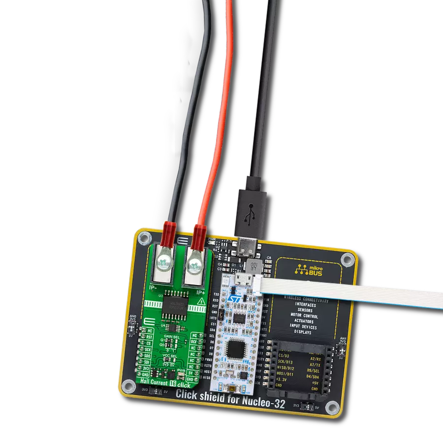
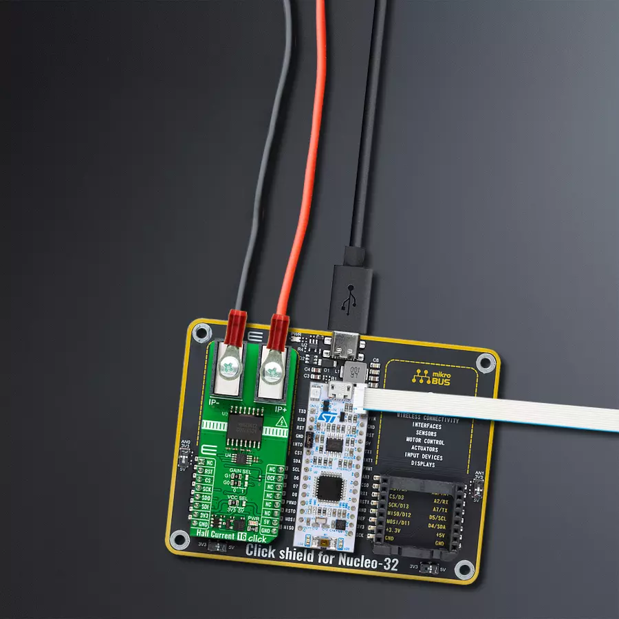
Hall Current 16 Click is based on the ACS37002, a 400kHz high-accuracy current sensor from Allegro Microsystems. It is a fully integrated Hall-effect current sensor, factory-trimmed to provide high accuracy over the entire operating range without user programming. The current is sensed differentially by two Hall plates that subtract out interfering external common mode magnetic fields. The Hall sensor has no physical connection to the integrated current conductor, as the ACS37002 provides high isolation by magnetically coupling the field generated by the current in the conductor. The current sensor features overvoltage detection, overcurrent fault, temperature compensation, and more. The ACS37002 is rated to withstand 3125VRMS of dielectric voltage. The IP+ and IP-
terminals are fused internally and allow connecting the load over the load connectors. Depending on the position of the two GAIN SEL jumpers, the gain can be set as high as 66.7A for IP as a maximum. By default, the gain is set to 0 position on both jumpers, which results in a 50A bidirectional gain. The sensitivity can range from 19.8 to 39.6mV/A depending on the chosen gain. The current sensor on the Hall Current 16 Click sends its output along with the zero current voltage reference to the ADC122S101, a two-channel 12-bit A/D converter from Texas Instruments. This ADC is fully specified over a sample rate range of 500ksps to 1Msps. It is based on a successive/approximation register architecture with an internal track-an-hold circuit. Hall Current 16 Click uses a standard 4-Wire SPI
serial interface of the ADC122S101 to communicate with the host MCU. If the sensed current exceeds the comparator threshold, the overcurrent fault (OCF) pin will trigger with an active LOW flag. The threshold can be set in percentage of full-scale output swing. You can turn off the overcurrent fault functionality. This Click board™ can operate with either 3.3V or 5V logic voltage levels selected via the PWR SEL jumper. This way, both 3.3V and 5V capable MCUs can use the communication lines properly. Also, this Click board™ comes equipped with a library containing easy-to-use functions and an example code that can be used as a reference for further development.


Features overview
Development board
Nucleo 32 with STM32F031K6 MCU board provides an affordable and flexible platform for experimenting with STM32 microcontrollers in 32-pin packages. Featuring Arduino™ Nano connectivity, it allows easy expansion with specialized shields, while being mbed-enabled for seamless integration with online resources. The
board includes an on-board ST-LINK/V2-1 debugger/programmer, supporting USB reenumeration with three interfaces: Virtual Com port, mass storage, and debug port. It offers a flexible power supply through either USB VBUS or an external source. Additionally, it includes three LEDs (LD1 for USB communication, LD2 for power,
and LD3 as a user LED) and a reset push button. The STM32 Nucleo-32 board is supported by various Integrated Development Environments (IDEs) such as IAR™, Keil®, and GCC-based IDEs like AC6 SW4STM32, making it a versatile tool for developers.

Microcontroller Overview
MCU Card / MCU

Architecture
ARM Cortex-M0
MCU Memory (KB)
32
Silicon Vendor
STMicroelectronics
Pin count
32
RAM (Bytes)
4096
You complete me!
Accessories
Click Shield for Nucleo-32 is the perfect way to expand your development board's functionalities with STM32 Nucleo-32 pinout. The Click Shield for Nucleo-32 provides two mikroBUS™ sockets to add any functionality from our ever-growing range of Click boards™. We are fully stocked with everything, from sensors and WiFi transceivers to motor control and audio amplifiers. The Click Shield for Nucleo-32 is compatible with the STM32 Nucleo-32 board, providing an affordable and flexible way for users to try out new ideas and quickly create prototypes with any STM32 microcontrollers, choosing from the various combinations of performance, power consumption, and features. The STM32 Nucleo-32 boards do not require any separate probe as they integrate the ST-LINK/V2-1 debugger/programmer and come with the STM32 comprehensive software HAL library and various packaged software examples. This development platform provides users with an effortless and common way to combine the STM32 Nucleo-32 footprint compatible board with their favorite Click boards™ in their upcoming projects.

Used MCU Pins
mikroBUS™ mapper
Take a closer look
Click board™ Schematic

Step by step
Project assembly

Start by selecting your development board and Click board™. Begin with the Nucleo 32 with STM32F031K6 MCU as your development board.


Software Support
Library Description
This library contains API for Hall Current 16 Click driver.
Key functions:
hallcurrent16_get_current- Hall Current 16 get current function.hallcurrent16_get_voltage- Hall Current 16 get voltage function.hallcurrent16_get_ovc_fault- Hall Current 16 get overcurrent fault function.
Open Source
Code example
The complete application code and a ready-to-use project are available through the NECTO Studio Package Manager for direct installation in the NECTO Studio. The application code can also be found on the MIKROE GitHub account.
/*!
* @file main.c
* @brief Hall Current 16 Click example
*
* # Description
* This example demonstrates the use of Hall Current 16 Click board
* by reading and displaying the current measurements.
*
* The demo application is composed of two sections :
*
* ## Application Init
* The initialization of SPI module and log UART.
* After driver initialization, the app sets the default configuration.
*
* ## Application Task
* The app reads the current measurements [A] and displays the results.
* Results are being sent to the UART Terminal, where you can track their changes.
*
* @author Nenad Filipovic
*
*/
#include "board.h"
#include "log.h"
#include "hallcurrent16.h"
static hallcurrent16_t hallcurrent16;
static log_t logger;
void application_init ( void )
{
log_cfg_t log_cfg; /**< Logger config object. */
hallcurrent16_cfg_t hallcurrent16_cfg; /**< Click config object. */
/**
* Logger initialization.
* Default baud rate: 115200
* Default log level: LOG_LEVEL_DEBUG
* @note If USB_UART_RX and USB_UART_TX
* are defined as HAL_PIN_NC, you will
* need to define them manually for log to work.
* See @b LOG_MAP_USB_UART macro definition for detailed explanation.
*/
LOG_MAP_USB_UART( log_cfg );
log_init( &logger, &log_cfg );
log_info( &logger, " Application Init " );
// Click initialization.
hallcurrent16_cfg_setup( &hallcurrent16_cfg );
HALLCURRENT16_MAP_MIKROBUS( hallcurrent16_cfg, MIKROBUS_1 );
if ( SPI_MASTER_ERROR == hallcurrent16_init( &hallcurrent16, &hallcurrent16_cfg ) )
{
log_error( &logger, " Communication init." );
for ( ; ; );
}
Delay_ms ( 100 );
if ( HALLCURRENT16_ERROR == hallcurrent16_default_cfg ( &hallcurrent16 ) )
{
log_error( &logger, " Default configuration." );
for ( ; ; );
}
log_info( &logger, " Application Task " );
log_printf( &logger, " -------------------- \r\n" );
Delay_ms ( 100 );
}
void application_task ( void )
{
static float current = 0.0;
if ( HALLCURRENT16_OK == hallcurrent16_get_current( &hallcurrent16, ¤t ) )
{
log_printf( &logger, " Current : %.3f A \r\n", current );
}
log_printf( &logger, " -------------------- \r\n" );
Delay_ms ( 1000 );
}
int main ( void )
{
/* Do not remove this line or clock might not be set correctly. */
#ifdef PREINIT_SUPPORTED
preinit();
#endif
application_init( );
for ( ; ; )
{
application_task( );
}
return 0;
}
// ------------------------------------------------------------------------ END
Additional Support
Resources
Category:Current sensor


