Monitor the movement of critical magnetic components using A1359 and STM32F031K6
Contactless magnetic position sensing

Published Oct 01, 2024
Click board™
Magneto 9 Click
Dev. board
Nucleo 32 with STM32F031K6 MCU
Compiler
NECTO Studio
MCU
STM32F031K6
Experience the future of magnetic sensing technology with our innovative solution, designed to monitor magnetic fields, magnet motion, and rotational angles for a wide range of applications
A
A
Hardware Overview
How does it work?
Magneto 9 Click is based on the A1359, a one-time programmable, dual tracking output, linear Hall-effect sensor from Allegro MicroSystems. It provides a dual analog/PWM output, where the PWM output tracks the analog output to within a +/-3% mismatch. It comes with factory-programmed output polarity; in this case, a forward polarity, meaning that output voltage increases with increasing positive (south) applied magnetic field. The A1359 targets the automotive market with end applications, including electronic power steering (torque sensing), transmission component position, brake and clutch cylinder
position, and various other industrial applications. The analog output signal of the A1359 can be converted to a digital value using MCP3221, a successive approximation A/D converter with a 12-bit resolution from Microchip, using a 2-wire I2C compatible interface, or can be sent directly to an analog pin of the mikroBUS™ socket labeled as AN. Selection can be performed by onboard SMD jumper labeled AD SEL to an appropriate position marked as AN and ADC. The MCP3221 provides one single-ended input with low power consumption, a low maximum conversion current, and a Standby current of 250μA and 1μA,
respectively. Data can be transferred at up to 100kbit/s in the Standard and 400kbit/s in the Fast Mode. Also, maximum sample rates of 22.3kSPS with the MCP3221 are possible in a Continuous-Conversion Mode with a clock rate of 400kHz. This Click board™ can be operated only with a 5V logic voltage level. The board must perform appropriate logic voltage level conversion before using MCUs with different logic levels. Also, it comes equipped with a library containing functions and an example code that can be used as a reference for further development.


Features overview
Development board
Nucleo 32 with STM32F031K6 MCU board provides an affordable and flexible platform for experimenting with STM32 microcontrollers in 32-pin packages. Featuring Arduino™ Nano connectivity, it allows easy expansion with specialized shields, while being mbed-enabled for seamless integration with online resources. The
board includes an on-board ST-LINK/V2-1 debugger/programmer, supporting USB reenumeration with three interfaces: Virtual Com port, mass storage, and debug port. It offers a flexible power supply through either USB VBUS or an external source. Additionally, it includes three LEDs (LD1 for USB communication, LD2 for power,
and LD3 as a user LED) and a reset push button. The STM32 Nucleo-32 board is supported by various Integrated Development Environments (IDEs) such as IAR™, Keil®, and GCC-based IDEs like AC6 SW4STM32, making it a versatile tool for developers.

Microcontroller Overview
MCU Card / MCU

Architecture
ARM Cortex-M0
MCU Memory (KB)
32
Silicon Vendor
STMicroelectronics
Pin count
32
RAM (Bytes)
4096
You complete me!
Accessories
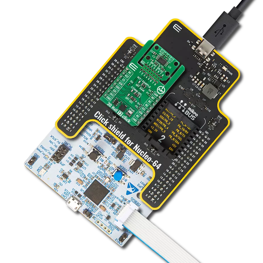
Click Shield for Nucleo-32 is the perfect way to expand your development board's functionalities with STM32 Nucleo-32 pinout. The Click Shield for Nucleo-32 provides two mikroBUS™ sockets to add any functionality from our ever-growing range of Click boards™. We are fully stocked with everything, from sensors and WiFi transceivers to motor control and audio amplifiers. The Click Shield for Nucleo-32 is compatible with the STM32 Nucleo-32 board, providing an affordable and flexible way for users to try out new ideas and quickly create prototypes with any STM32 microcontrollers, choosing from the various combinations of performance, power consumption, and features. The STM32 Nucleo-32 boards do not require any separate probe as they integrate the ST-LINK/V2-1 debugger/programmer and come with the STM32 comprehensive software HAL library and various packaged software examples. This development platform provides users with an effortless and common way to combine the STM32 Nucleo-32 footprint compatible board with their favorite Click boards™ in their upcoming projects.

Used MCU Pins
mikroBUS™ mapper
Take a closer look
Click board™ Schematic

Step by step
Project assembly

Start by selecting your development board and Click board™. Begin with the Nucleo 32 with STM32F031K6 MCU as your development board.


Track your results in real time
Application Output
1. Application Output - In Debug mode, the 'Application Output' window enables real-time data monitoring, offering direct insight into execution results. Ensure proper data display by configuring the environment correctly using the provided tutorial.

2. UART Terminal - Use the UART Terminal to monitor data transmission via a USB to UART converter, allowing direct communication between the Click board™ and your development system. Configure the baud rate and other serial settings according to your project's requirements to ensure proper functionality. For step-by-step setup instructions, refer to the provided tutorial.

3. Plot Output - The Plot feature offers a powerful way to visualize real-time sensor data, enabling trend analysis, debugging, and comparison of multiple data points. To set it up correctly, follow the provided tutorial, which includes a step-by-step example of using the Plot feature to display Click board™ readings. To use the Plot feature in your code, use the function: plot(*insert_graph_name*, variable_name);. This is a general format, and it is up to the user to replace 'insert_graph_name' with the actual graph name and 'variable_name' with the parameter to be displayed.

Software Support
Library Description
This library contains API for Magneto 9 Click driver.
Key functions:
magneto9_read_adc_voltage- This function reads raw 12-bit ADC data and converts it to voltage by using I2C serial interfacemagneto9_read_an_pin_voltage- This function reads results of AD conversion of the AN pin and converts them to proportional voltage levelmagneto9_get_pwm_pin- This function returns the PWM pin logic state.
Open Source
Code example
The complete application code and a ready-to-use project are available through the NECTO Studio Package Manager for direct installation in the NECTO Studio. The application code can also be found on the MIKROE GitHub account.
/*!
 * @file main.c
 * @brief Magneto 9 Click Example.
 *
 * # Description
 * This example demonstrates the use of Magneto 9 Click board.
 *
 * The demo application is composed of two sections :
 *
 * ## Application Init
 * Initializes the driver and logger.
 *
 * ## Application Task
 * Reads the ADC voltage and calculates the magnetic field strength from it.
 * Voltage increases with increasing positive (south) applied magnetic field.
 * All data are being displayed on the USB UART where you can track their changes.
 *
 * @author Stefan Filipovic
 *
 */

#include "board.h"
#include "log.h"
#include "magneto9.h"

static magneto9_t magneto9;   /**< Magneto 9 Click driver object. */
static log_t logger;          /**< Logger object. */

void application_init ( void )
{
    log_cfg_t log_cfg;            /**< Logger config object. */
    magneto9_cfg_t magneto9_cfg;  /**< Click config object. */

    /**
     * Logger initialization.
     * Default baud rate: 115200
     * Default log level: LOG_LEVEL_DEBUG
     * @note If USB_UART_RX and USB_UART_TX
     * are defined as HAL_PIN_NC, you will
     * need to define them manually for log to work.
     * See @b LOG_MAP_USB_UART macro definition for detailed explanation.
     */
    LOG_MAP_USB_UART( log_cfg );
    log_init( &logger, &log_cfg );
    Delay_ms ( 100 );
    log_info( &logger, " Application Init " );

    // Click initialization.
    magneto9_cfg_setup( &magneto9_cfg );
    MAGNETO9_MAP_MIKROBUS( magneto9_cfg, MIKROBUS_1 );
    if ( ADC_ERROR == magneto9_init( &magneto9, &magneto9_cfg ) )
    {
        log_error( &logger, " Application Init Error. " );
        log_info( &logger, " Please, run program again... " );

        for ( ; ; );
    }
    log_info( &logger, " Application Task " );
}

void application_task ( void )
{
    float voltage = 0;

    if ( MAGNETO9_OK == magneto9_read_an_pin_voltage ( &magneto9, &voltage ) )
    {
        float field_strength = MAGNETO9_VOLTAGE_TO_FIELD_STRENGTH ( voltage );
        log_printf( &logger, " ADC Voltage : %.3f V\r\n", voltage );
        log_printf( &logger, " Magnetic field strength : %.3f mT\r\n", field_strength );
        if ( field_strength < 0 )
        {
            log_printf( &logger, " The North Pole magnetic field prevails.\r\n\n" );
        }
        else
        {
            log_printf( &logger, " The South Pole magnetic field prevails.\r\n\n" );
        }
    }
    Delay_ms ( 1000 );
}

int main ( void )
{
    /* Do not remove this line or clock might not be set correctly. */
    #ifdef PREINIT_SUPPORTED
    preinit();
    #endif

    application_init( );

    for ( ; ; )
    {
        application_task( );
    }

    return 0;
}

// ------------------------------------------------------------------------ END
Additional Support
Resources
Category:Magnetic