Monitor your heart rate with OB1203 and TM4C129ENCPDT
Your heart, your engine!
Published Mar 12, 2023
Click board™
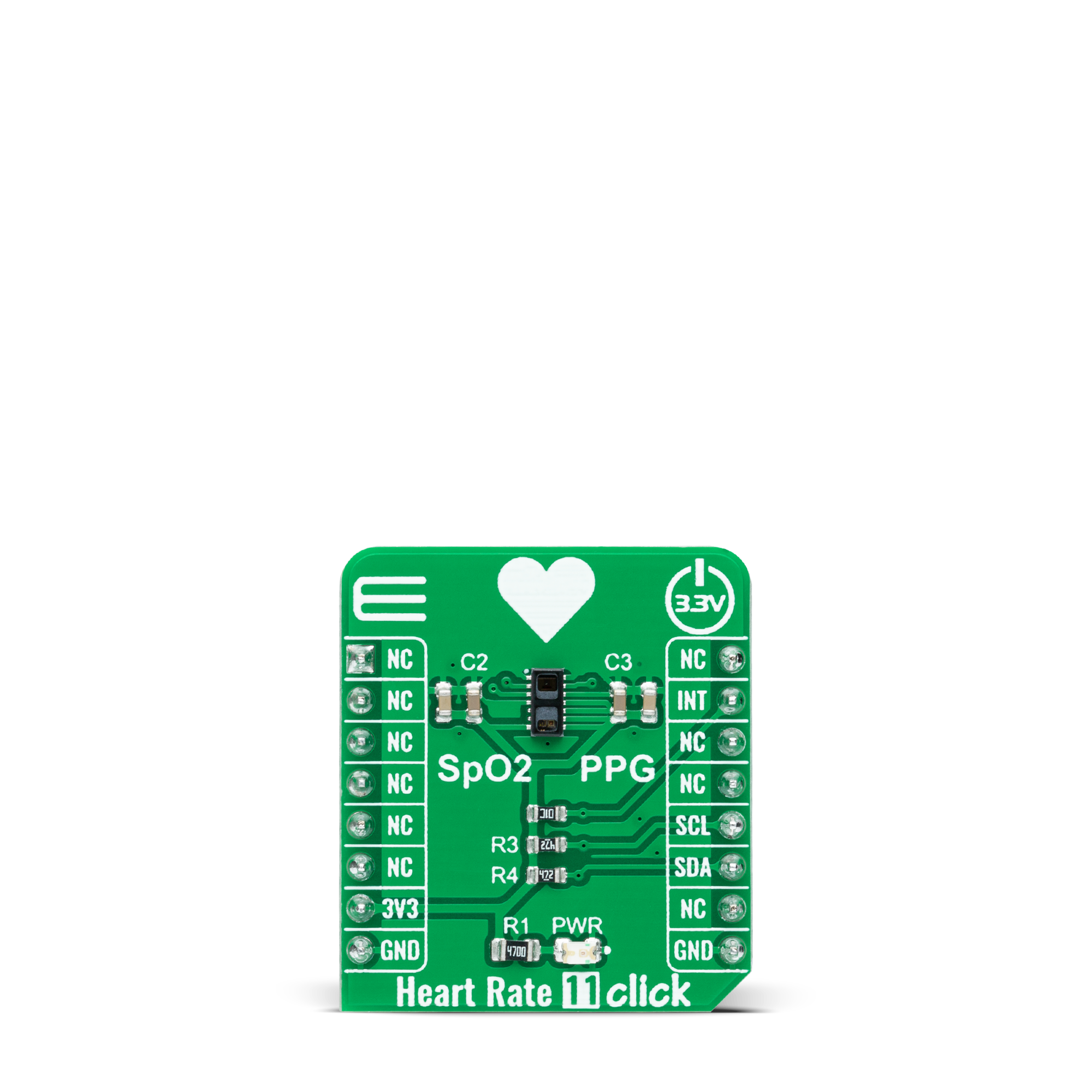
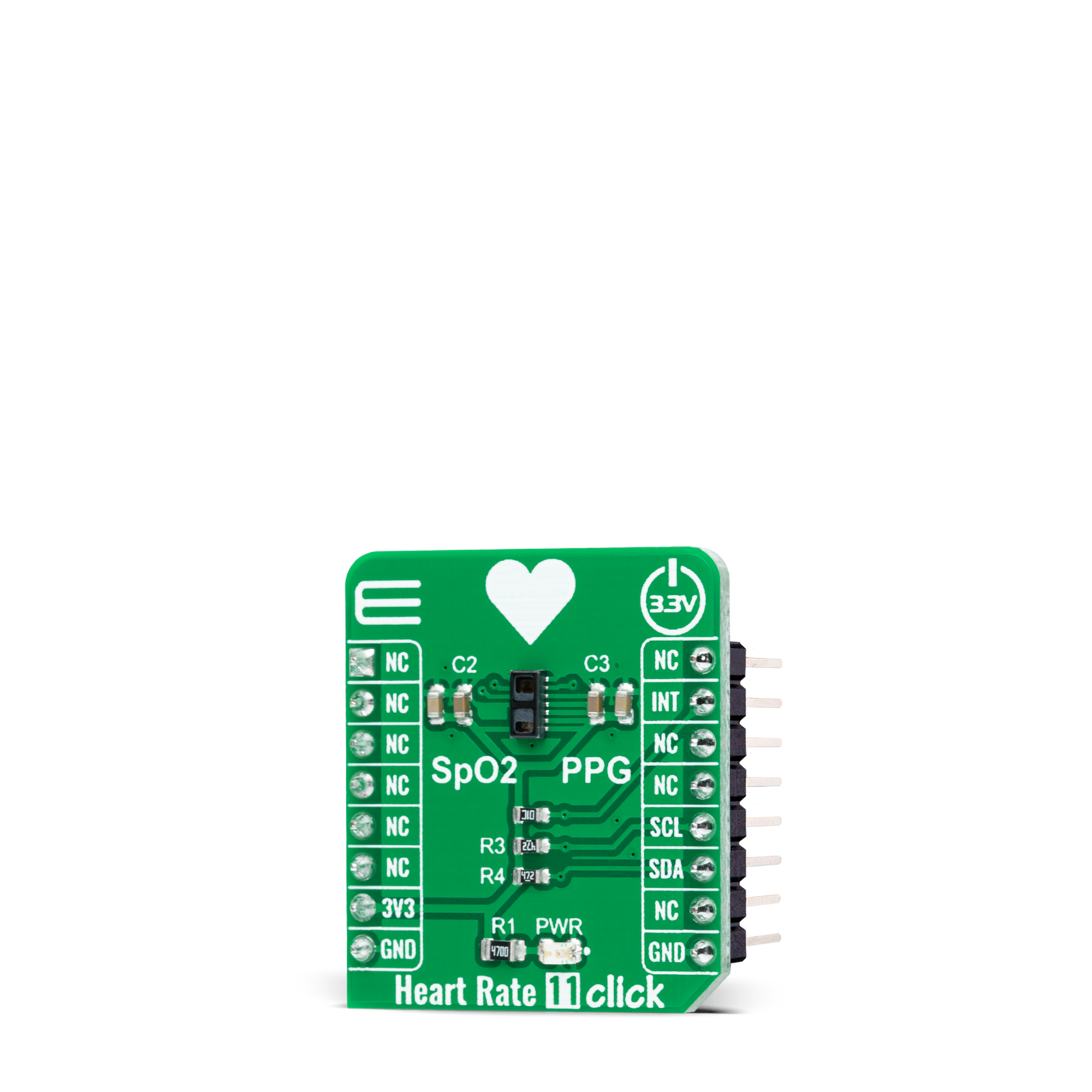
Heart Rate 11 Click
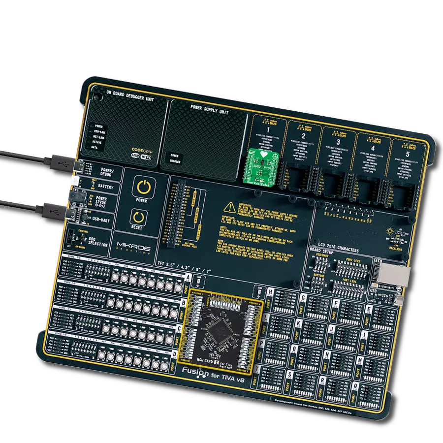
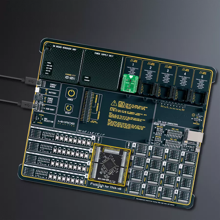
Dev. board
Fusion for Tiva v8
Compiler
NECTO Studio
MCU
TM4C129ENCPDT
Determine your heart rate and oxygen saturation in the simplest possible way
A
A
Hardware Overview
How does it work?
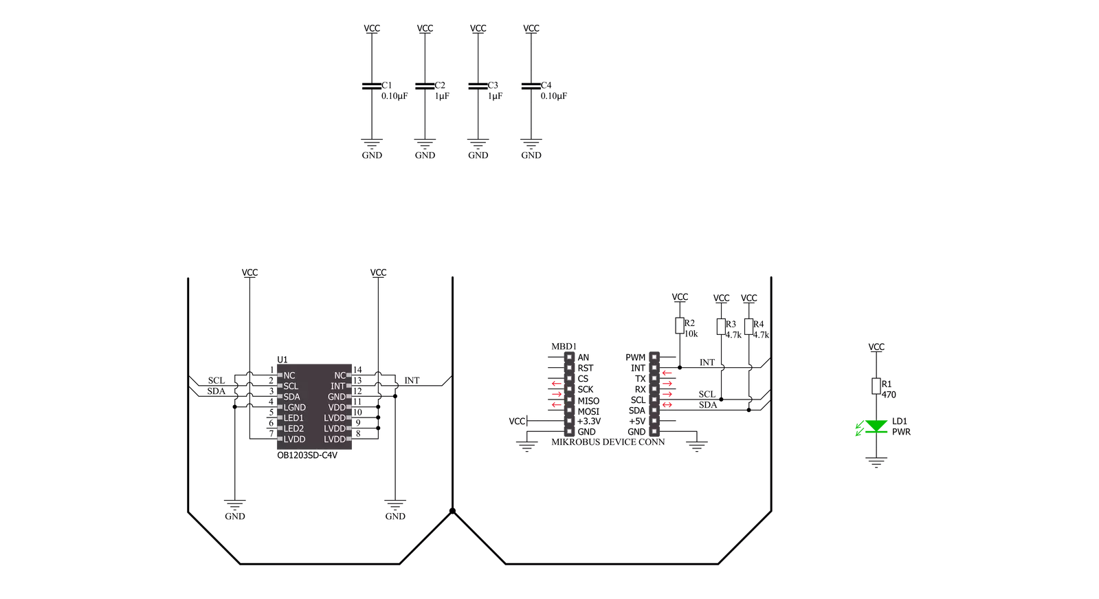
Heart Rate 11 Click is based on the OB1203, a fully integrated all-in-one biosensor module that measures heart rate and blood oxygen levels from Renesas. The OB1203 combines all light sources, drivers, and sensor elements, in a single optically optimized package. It can be used with just one side of a user's finger because it uses the space-conserving reflective PPG method. The appropriate algorithm can determine human heart rate, respiration rate, and heart rate variability (a measure of stress) or blood oxygen saturation (SpO2) behind IR transmissive but visibly dark ink, allowing implementation in aesthetic industrial designs.
The biosensor module contains different photodiodes for light (R, G, B, and Clear channels), proximity measurements, photoplethysmography, and temperature compensation of the light sensor. Those diodes are arranged in a matrix array, while the single diode for PS/PPG measurement is below the matrix. The photodiode current is converted to digital values by an analog-to-digital converter (ADC) and then forwarded via a serial interface for further processing. The OB1203 communicates with MCU using the standard I2C 2-Wire interface with a maximum clock frequency of 400kHz, fully adjustable through software registers.
Also, it uses an interrupt pin, the INT pin of the mikroBUS™ socket, indicating when a specific interrupt event occurs, such as light, proximity, or photoplethysmography threshold crossed. This Click board™ can only be operated with a 3.3V logic voltage level. The board must perform appropriate logic voltage level conversion before using MCUs with different logic levels. However, the Click board™ comes equipped with a library containing functions and an example code that can be used as a reference for further development.

Features overview
Development board
Fusion for TIVA v8 is a development board specially designed for the needs of rapid development of embedded applications. It supports a wide range of microcontrollers, such as different 32-bit ARM® Cortex®-M based MCUs from Texas Instruments, regardless of their number of pins, and a broad set of unique functions, such as the first-ever embedded debugger/programmer over a WiFi network. The development board is well organized and designed so that the end-user has all the necessary elements, such as switches, buttons, indicators, connectors, and others, in one place. Thanks to innovative manufacturing technology, Fusion for TIVA v8 provides a fluid and immersive working experience, allowing access
anywhere and under any circumstances at any time. Each part of the Fusion for TIVA v8 development board contains the components necessary for the most efficient operation of the same board. An advanced integrated CODEGRIP programmer/debugger module offers many valuable programming/debugging options, including support for JTAG, SWD, and SWO Trace (Single Wire Output)), and seamless integration with the Mikroe software environment. Besides, it also includes a clean and regulated power supply module for the development board. It can use a wide range of external power sources, including a battery, an external 12V power supply, and a power source via the USB Type-C (USB-C) connector.
Communication options such as USB-UART, USB HOST/DEVICE, CAN (on the MCU card, if supported), and Ethernet is also included. In addition, it also has the well-established mikroBUS™ standard, a standardized socket for the MCU card (SiBRAIN standard), and two display options for the TFT board line of products and character-based LCD. Fusion for TIVA v8 is an integral part of the Mikroe ecosystem for rapid development. Natively supported by Mikroe software tools, it covers many aspects of prototyping and development thanks to a considerable number of different Click boards™ (over a thousand boards), the number of which is growing every day.

Microcontroller Overview
MCU Card / MCU

Type
8th Generation
Architecture
ARM Cortex-M4
MCU Memory (KB)
1024
Silicon Vendor
Texas Instruments
Pin count
128
RAM (Bytes)
262144
Used MCU Pins
mikroBUS™ mapper
Take a closer look
Click board™ Schematic
Step by step
Project assembly

Start by selecting your development board and Click board™. Begin with the Fusion for Tiva v8 as your development board.


Software Support
Library Description
This library contains API for Heart Rate 11 Click driver.
Key functions:
heartrate11_get_int_pinThis function returns the INT pin logic state.heartrate11_set_led_currentThis function sets the maximal current of the selected LED.heartrate11_read_fifoThis function reads a 24-bit data from the FIFO.
Open Source
Code example
The complete application code and a ready-to-use project are available through the NECTO Studio Package Manager for direct installation in the NECTO Studio. The application code can also be found on the MIKROE GitHub account.
/*!
 * @file main.c
 * @brief HeartRate11 Click example
 *
 * # Description
 * This example demonstrates the use of Heart Rate 11 Click board by reading and displaying
 * the PPG1 (HR) values which can be visualized on the SerialPlot application.
 *
 * The demo application is composed of two sections :
 *
 * ## Application Init
 * Initializes the driver and performs the Click default configuration for heart rate measurement.
 *
 * ## Application Task
 * Waits for the data ready interrupt, then reads the values of PPG from FIFO and displays it on the
 * USB UART (SerialPlot) every 32ms approximately.
 *
 * @note
 * We recommend using the SerialPlot tool for data visualizing.
 *
 * @author Stefan Filipovic
 *
 */

#include "board.h"
#include "log.h"
#include "heartrate11.h"

static heartrate11_t heartrate11;
static log_t logger;

void application_init ( void )
{
    log_cfg_t log_cfg;  /**< Logger config object. */
    heartrate11_cfg_t heartrate11_cfg;  /**< Click config object. */

    /**
     * Logger initialization.
     * Default baud rate: 115200
     * Default log level: LOG_LEVEL_DEBUG
     * @note If USB_UART_RX and USB_UART_TX
     * are defined as HAL_PIN_NC, you will
     * need to define them manually for log to work.
     * See @b LOG_MAP_USB_UART macro definition for detailed explanation.
     */
    LOG_MAP_USB_UART( log_cfg );
    log_init( &logger, &log_cfg );
    log_info( &logger, " Application Init " );

    // Click initialization.
    heartrate11_cfg_setup( &heartrate11_cfg );
    HEARTRATE11_MAP_MIKROBUS( heartrate11_cfg, MIKROBUS_1 );
    if ( I2C_MASTER_ERROR == heartrate11_init( &heartrate11, &heartrate11_cfg ) )
    {
        log_error( &logger, " Communication init." );
        for ( ; ; );
    }

    if ( HEARTRATE11_ERROR == heartrate11_default_cfg ( &heartrate11 ) )
    {
        log_error( &logger, " Default configuration." );
        for ( ; ; );
    }

    log_info( &logger, " Application Task " );
}

void application_task ( void )
{
    // Wait for the data ready interrupt indication
    while ( heartrate11_get_int_pin ( &heartrate11 ) );

    uint32_t ppg;
    if ( HEARTRATE11_OK == heartrate11_read_fifo ( &heartrate11, &ppg ) )
    {
        log_printf ( &logger, "%lu\r\n", ppg );
    }
}

int main ( void )
{
    /* Do not remove this line or clock might not be set correctly. */
    #ifdef PREINIT_SUPPORTED
    preinit();
    #endif

    application_init( );

    for ( ; ; )
    {
        application_task( );
    }

    return 0;
}

// ------------------------------------------------------------------------ END
Additional Support
Resources
Category:Biometrics


