Recognize the following gestures with MAX25405 and MK64FN1M0VDC12
Contactless gesture recognition
Published Mar 11, 2023
Click board™
IR Gesture 2 Click
Dev. board
Fusion for Kinetis v8
Compiler
NECTO Studio
MCU
MK64FN1M0VDC12
One solution for proximity, hand detection, and gesture recognition
A
A
Hardware Overview
How does it work?
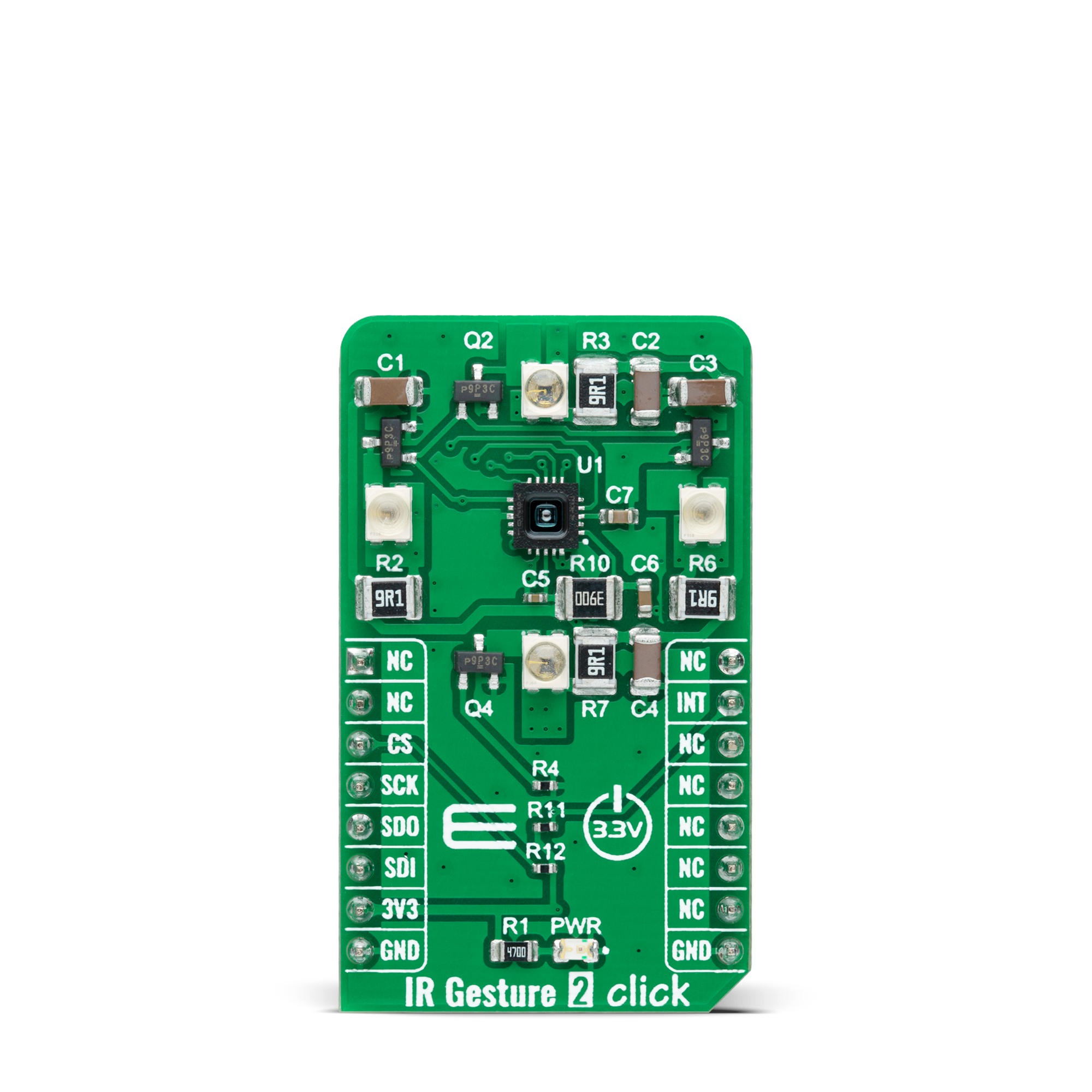
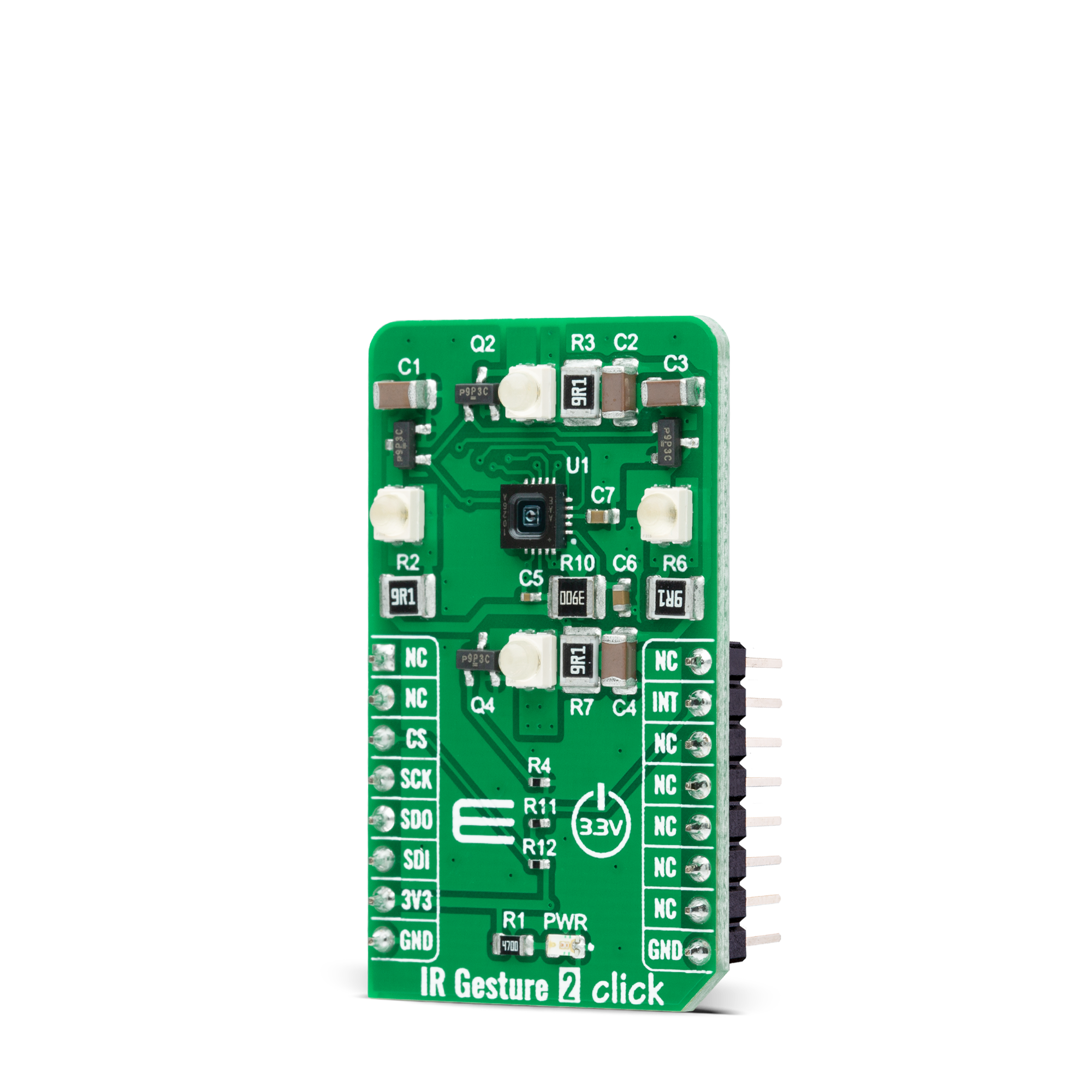
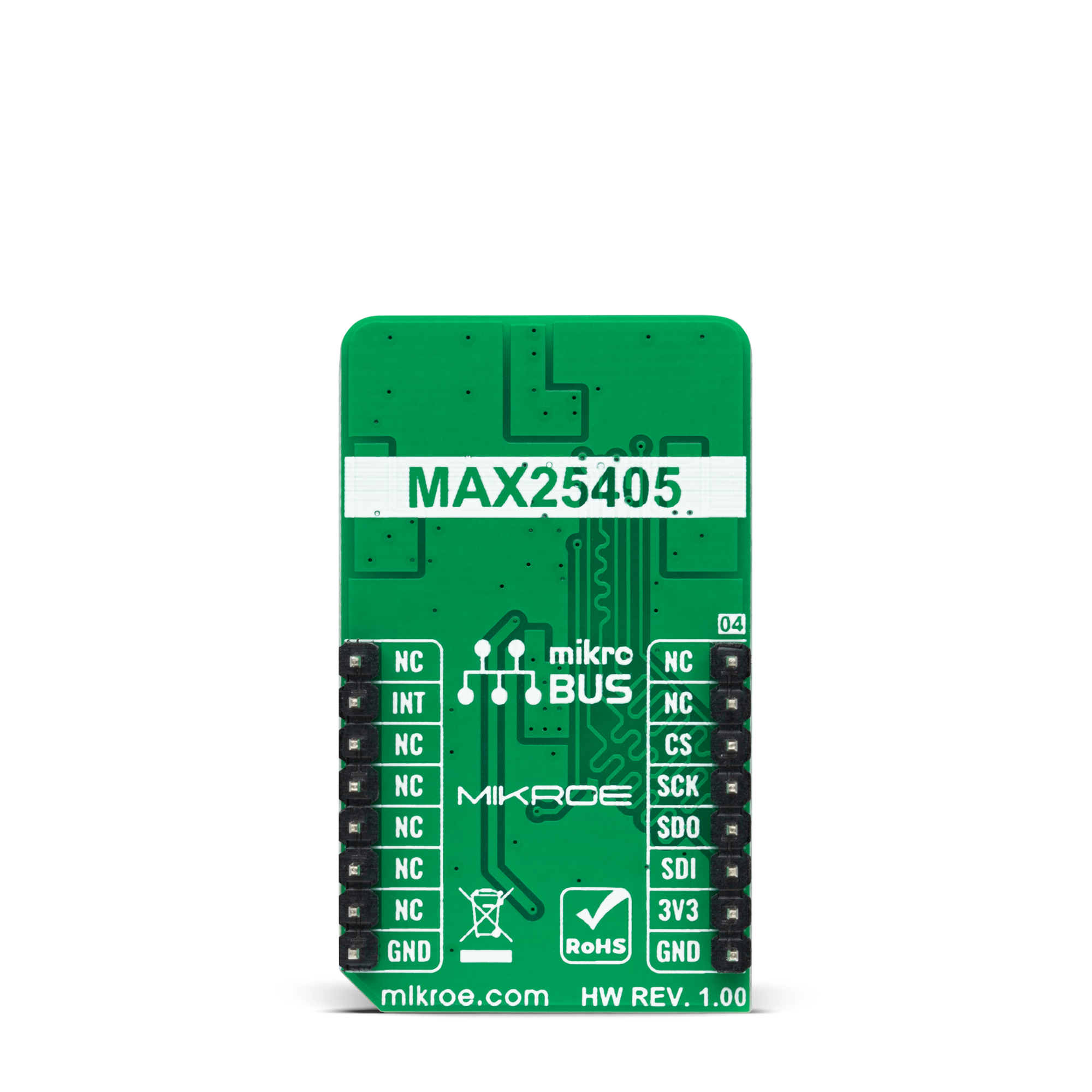
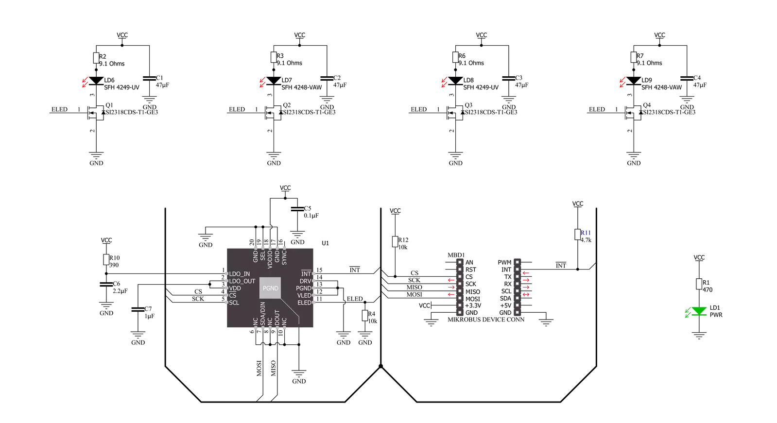
IR Gesture 2 Click is based on the MAX25405 data-acquisition system from Analog Devices for gesture and proximity sensing. This Click board™ represents an infrared-based dynamic optical solution that can sense a broader range of motions at extended distances. The MAX25405 detects wider movement proximity and doubles the sensing range to 40cm compared to earlier generations. It recognizes the following independent gestures: hand swipe (left, right, up, down, wave), air click and flicks, finger and hand rotation (clockwise and counter-clockwise), and multizone proximity detection. Along with integrated optics and a 6x10 infrared sensor array, the MAX25405 also includes a glass lens,
increasing sensitivity and improving the signal-to-noise ratio. The proximity, hand detection, and gesture recognition functions of the MAX25405 operate by detecting the light reflected from the controlled IR-LED light sources (SFH 4248-VAW and SFH 4249-UV) driven directly from the MAX25405. It can also detect these gestures even when exposed to bright ambient light and process data from the sensor through a serial interface. The light source PWM duty cycle is programmable from 1/16 to 16/16, where LEDs are pulsed one or more times in a programmable sequence repeated for every sample. IR Gesture 2 Click communicates with MCU using the 12-bit SPI serial interface compatible with
standard SPI, QSPI™, MICROWIRE™, and digital signal processors (DSPs), with a maximum frequency of 6MHz. This Click board™ also possesses an additional interrupt pin, routed to the INT pin on the mikroBUS™ socket, indicating when a specific interrupt event occurs, such as the end of a conversation sample sequence. This Click board™ can only be operated with a 3.3V logic voltage level. The board must perform appropriate logic voltage level conversion before using MCUs with different logic levels. However, the Click board™ comes equipped with a library containing functions and an example code that can be used as a reference for further development.
Features overview
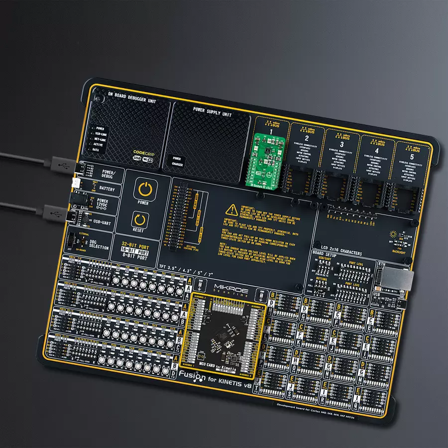
Development board
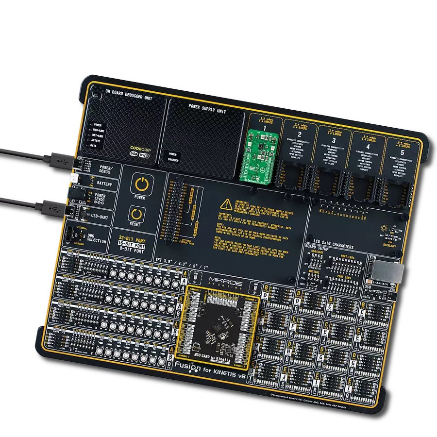
Fusion for KINETIS v8 is a development board specially designed for the needs of rapid development of embedded applications. It supports a wide range of microcontrollers, such as different 32-bit ARM® Cortex®-M based MCUs from NXP Semiconductor, regardless of their number of pins, and a broad set of unique functions, such as the first-ever embedded debugger/programmer over a WiFi network. The development board is well organized and designed so that the end-user has all the necessary elements, such as switches, buttons, indicators, connectors, and others, in one place. Thanks to innovative manufacturing technology, Fusion for KINETIS v8 provides a fluid and immersive working experience, allowing
access anywhere and under any circumstances at any time. Each part of the Fusion for KINETIS v8 development board contains the components necessary for the most efficient operation of the same board. An advanced integrated CODEGRIP programmer/debugger module offers many valuable programming/debugging options, including support for JTAG, SWD, and SWO Trace (Single Wire Output)), and seamless integration with the Mikroe software environment. Besides, it also includes a clean and regulated power supply module for the development board. It can use a wide range of external power sources, including a battery, an external 12V power supply, and a power source via the USB Type-C (USB-C) connector.
Communication options such as USB-UART, USB HOST/DEVICE, CAN (on the MCU card, if supported), and Ethernet is also included. In addition, it also has the well-established mikroBUS™ standard, a standardized socket for the MCU card (SiBRAIN standard), and two display options for the TFT board line of products and character-based LCD. Fusion for KINETIS v8 is an integral part of the Mikroe ecosystem for rapid development. Natively supported by Mikroe software tools, it covers many aspects of prototyping and development thanks to a considerable number of different Click boards™ (over a thousand boards), the number of which is growing every day.

Microcontroller Overview
MCU Card / MCU
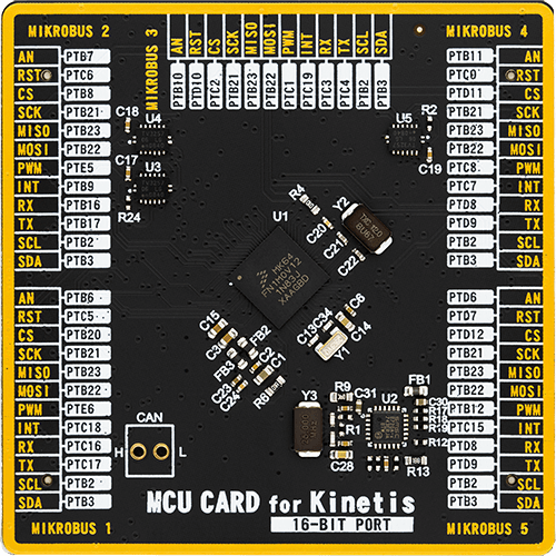
Type
8th Generation
Architecture
ARM Cortex-M4
MCU Memory (KB)
1024
Silicon Vendor
NXP
Pin count
121
RAM (Bytes)
262144
Used MCU Pins
mikroBUS™ mapper
Take a closer look
Click board™ Schematic
Step by step
Project assembly

Start by selecting your development board and Click board™. Begin with the Fusion for Kinetis v8 as your development board.


Software Support
Library Description
This library contains API for IR Gesture 2 Click driver.
Key functions:
irgesture2_get_int_pinThis function returns the INT pin logic state.irgesture2_read_pixelsThis function reads the raw ADC values of entire 60-pixel IR photodiode array.irgesture2_write_registerThis function writes a data byte to the selected register by using SPI serial interface.
Open Source
Code example
The complete application code and a ready-to-use project are available through the NECTO Studio Package Manager for direct installation in the NECTO Studio. The application code can also be found on the MIKROE GitHub account.
/*!
 * @file main.c
 * @brief IRGesture2 Click example
 *
 * # Description
 * This example demonstrates the use of IR Gesture 2 Click board by reading and displaying
 * the raw ADC values of entire 60-pixel IR photodiode array.
 *
 * The demo application is composed of two sections :
 *
 * ## Application Init
 * Initializes the driver and performs the Click default configuration.
 *
 * ## Application Task
 * Waits for an end of conversion interrupt and then reads the raw ADC values of entire
 * 60-pixel IR photodiode array and displays the results on the USB UART as a 10x6 matrix
 * every 100ms approximately.
 *
 * @author Stefan Filipovic
 *
 */

#include "board.h"
#include "log.h"
#include "irgesture2.h"

static irgesture2_t irgesture2;
static log_t logger;

void application_init ( void )
{
    log_cfg_t log_cfg;  /**< Logger config object. */
    irgesture2_cfg_t irgesture2_cfg;  /**< Click config object. */

    /**
     * Logger initialization.
     * Default baud rate: 115200
     * Default log level: LOG_LEVEL_DEBUG
     * @note If USB_UART_RX and USB_UART_TX
     * are defined as HAL_PIN_NC, you will
     * need to define them manually for log to work.
     * See @b LOG_MAP_USB_UART macro definition for detailed explanation.
     */
    LOG_MAP_USB_UART( log_cfg );
    log_init( &logger, &log_cfg );
    log_info( &logger, " Application Init " );

    // Click initialization.
    irgesture2_cfg_setup( &irgesture2_cfg );
    IRGESTURE2_MAP_MIKROBUS( irgesture2_cfg, MIKROBUS_1 );
    if ( SPI_MASTER_ERROR == irgesture2_init( &irgesture2, &irgesture2_cfg ) )
    {
        log_error( &logger, " Communication init." );
        for ( ; ; );
    }

    if ( IRGESTURE2_ERROR == irgesture2_default_cfg ( &irgesture2 ) )
    {
        log_error( &logger, " Default configuration." );
        for ( ; ; );
    }

    log_info( &logger, " Application Task " );
}

void application_task ( void )
{
    // Wait for an end of conversion interrupt
    while ( irgesture2_get_int_pin ( &irgesture2 ) );

    int16_t pixels[ IRGESTURE2_NUM_SENSOR_PIXELS ];
    if ( IRGESTURE2_OK == irgesture2_read_pixels ( &irgesture2, pixels, false ) )
    {
        for ( uint8_t cnt = 0; cnt < IRGESTURE2_NUM_SENSOR_PIXELS; cnt++ )
        {
            if ( 0 == ( cnt % IRGESTURE2_SENSOR_X_SIZE ) )
            {
                log_printf( &logger, "\r\n" );
            }
            log_printf( &logger, "%d\t", pixels[ cnt ] );
        }
        log_printf( &logger, "\r\n" );
    }
}

int main ( void )
{
    /* Do not remove this line or clock might not be set correctly. */
    #ifdef PREINIT_SUPPORTED
    preinit();
    #endif

    application_init( );

    for ( ; ; )
    {
        application_task( );
    }

    return 0;
}

// ------------------------------------------------------------------------ END
Additional Support
Resources
Category:Motion


