Detect objects and achieve presence awareness up to 200 millimeters with the VCNL36828P and STM32F469II
Short-range proximity sensing applications up to 200mm

Published Jul 23, 2024
Click board™
Proximity 20 Click
Dev. board
Fusion for STM32 v8
Compiler
NECTO Studio
MCU
STM32F469II
Detect the presence or absence of objects within a 200mm range, ideal for gesture recognition and object avoidance applications
A
A
Hardware Overview
How does it work?
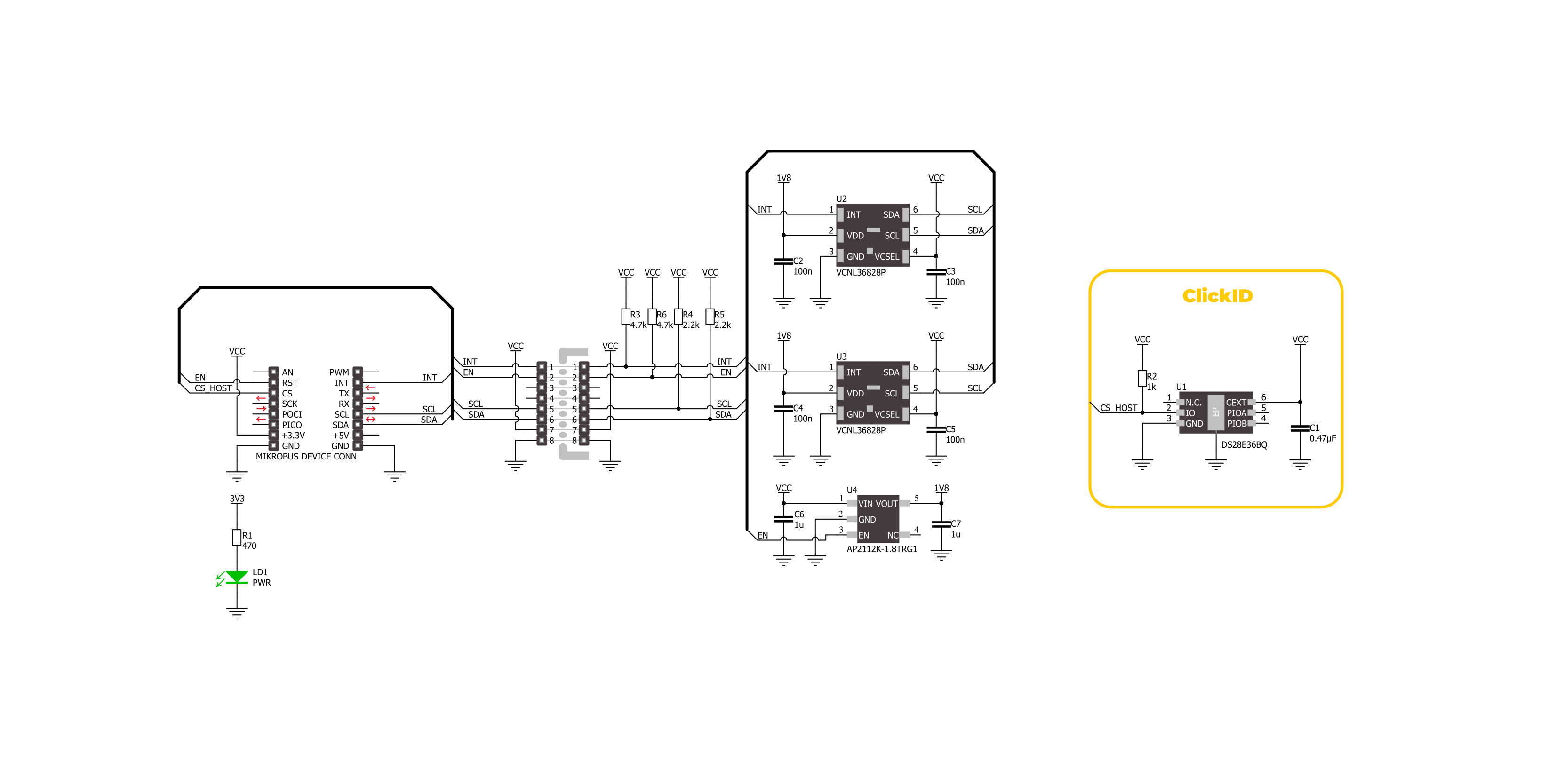
Proximity 20 Click is based on two VCNL36828Ps, fully integrated proximity sensors from Vishay Semiconductor, designed for low power consumption and short-range operation up to 200mm. Each VCNL36828P integrates a vertical-cavity surface-emitting laser (VCSEL), photodiode, and application-specific integrated circuit (ASIC) within a single package. Notable features include immunity to red glow thanks to the 940nm VCSEL, intelligent cancellation technology that minimizes cross talk, and a smart persistence scheme designed to reduce measurement response time. The VCNL36828P also features a smart dual slave address capability, enabling users to switch addresses by simply swapping the SCL and SDA pins. This flexibility is the reason why this Click board™ incorporates two identical sensors. Proximity 20 Click is designed in a unique format
supporting the newly introduced MIKROE feature called "Click Snap." Unlike the standardized version of Click boards, this feature allows the main IC area to become movable by breaking the PCB, opening up many new possibilities for implementation. Thanks to the Snap feature, the VCNL36828Ps can operate autonomously by accessing its signals directly on the pins marked 1-8. Additionally, the Snap part includes a specified and fixed screw hole position, enabling users to secure the Snap board in their desired location. This Click board™ uses a standard 2-wire I2C interface to communicate with the host MCU, supporting Standard mode with up to 400kHz of frequency clock. The I2C interface and registers allow for controlling various sensor functions, such as operating mode control, interrupt system management for interrupt signals available on INT
pin, and adjusting offset and threshold values for proximity sensor data. This flexibility ensures precise and customizable operations tailored to specific application needs. The VCNL36828Ps do not require a specific Power-Up sequence but require a voltage of 1.8V for its interface and logic part to work correctly. Therefore, a small regulating LDO, the AP2112, provides a 1.8V out of 3.3V mikroBUS™ power rail. This regulator can be activated via the EN pin of the mikroBUS™ socket, providing an enable function simultaneously. This Click board™ can be operated only with a 3.3V logic voltage level. The board must perform appropriate logic voltage level conversion before using MCUs with different logic levels. Also, it comes equipped with a library containing functions and an example code that can be used as a reference for further development.

Features overview
Development board
Fusion for STM32 v8 is a development board specially designed for the needs of rapid development of embedded applications. It supports a wide range of microcontrollers, such as different 32-bit ARM® Cortex®-M based MCUs from STMicroelectronics, regardless of their number of pins, and a broad set of unique functions, such as the first-ever embedded debugger/programmer over WiFi. The development board is well organized and designed so that the end-user has all the necessary elements, such as switches, buttons, indicators, connectors, and others, in one place. Thanks to innovative manufacturing technology, Fusion for STM32 v8 provides a fluid and immersive working experience, allowing
access anywhere and under any circumstances at any time. Each part of the Fusion for STM32 v8 development board contains the components necessary for the most efficient operation of the same board. An advanced integrated CODEGRIP programmer/debugger module offers many valuable programming/debugging options, including support for JTAG, SWD, and SWO Trace (Single Wire Output)), and seamless integration with the Mikroe software environment. Besides, it also includes a clean and regulated power supply module for the development board. It can use a wide range of external power sources, including a battery, an external 12V power supply, and a power source via the USB Type-C (USB-C) connector.
Communication options such as USB-UART, USB HOST/DEVICE, CAN (on the MCU card, if supported), and Ethernet is also included. In addition, it also has the well-established mikroBUS™ standard, a standardized socket for the MCU card (SiBRAIN standard), and two display options for the TFT board line of products and character-based LCD. Fusion for STM32 v8 is an integral part of the Mikroe ecosystem for rapid development. Natively supported by Mikroe software tools, it covers many aspects of prototyping and development thanks to a considerable number of different Click boards™ (over a thousand boards), the number of which is growing every day.

Microcontroller Overview
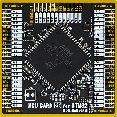
MCU Card / MCU
Type
8th Generation
Architecture
ARM Cortex-M4
MCU Memory (KB)
2048
Silicon Vendor
STMicroelectronics
Pin count
176
RAM (Bytes)
393216
Used MCU Pins
mikroBUS™ mapper
Take a closer look
Click board™ Schematic
Step by step
Project assembly

Start by selecting your development board and Click board™. Begin with the Fusion for STM32 v8 as your development board.


Software Support
Library Description
This library contains API for Proximity 20 Click driver.
Key functions:
proximity20_read_proximity- This function reads the proximity data from U2 and U3 sensors.proximity20_set_device_address- This function sets the device slave address.proximity20_enable_device- This function enables the device by setting the EN pin to high logic state.
Open Source
Code example
The complete application code and a ready-to-use project are available through the NECTO Studio Package Manager for direct installation in the NECTO Studio. The application code can also be found on the MIKROE GitHub account.
/*!
 * @file main.c
 * @brief Proximity 20 Click example
 *
 * # Description
 * This example demonstrates the use of Proximity 20 Click board by reading and
 * displaying the proximity data on the USB UART.
 *
 * The demo application is composed of two sections :
 *
 * ## Application Init
 * Initializes the driver and logger, and performs the Click default configuration.
 *
 * ## Application Task
 * Reads the proximity data from 2 sensors and displays the results on the USB UART every 200ms.
 * The higher the proximity value, the closer the detected object.
 *
 * @author Stefan Filipovic
 *
 */

#include "board.h"
#include "log.h"
#include "proximity20.h"

static proximity20_t proximity20;
static log_t logger;

void application_init ( void )
{
    log_cfg_t log_cfg;  /**< Logger config object. */
    proximity20_cfg_t proximity20_cfg;  /**< Click config object. */

    /**
     * Logger initialization.
     * Default baud rate: 115200
     * Default log level: LOG_LEVEL_DEBUG
     * @note If USB_UART_RX and USB_UART_TX
     * are defined as HAL_PIN_NC, you will
     * need to define them manually for log to work.
     * See @b LOG_MAP_USB_UART macro definition for detailed explanation.
     */
    LOG_MAP_USB_UART( log_cfg );
    log_init( &logger, &log_cfg );
    log_info( &logger, " Application Init " );

    // Click initialization.
    proximity20_cfg_setup( &proximity20_cfg );
    PROXIMITY20_MAP_MIKROBUS( proximity20_cfg, MIKROBUS_1 );
    if ( I2C_MASTER_ERROR == proximity20_init( &proximity20, &proximity20_cfg ) )
    {
        log_error( &logger, " Communication init." );
        for ( ; ; );
    }

    if ( PROXIMITY20_ERROR == proximity20_default_cfg ( &proximity20 ) )
    {
        log_error( &logger, " Default configuration." );
        for ( ; ; );
    }

    log_info( &logger, " Application Task " );
}

void application_task ( void )
{
    uint16_t ps_data_u2 = 0;
    uint16_t ps_data_u3 = 0;
    if ( PROXIMITY20_OK == proximity20_read_proximity ( &proximity20, &ps_data_u2, &ps_data_u3 ) )
    {
        log_printf ( &logger, " PS data [U2]: %u\r\n", ps_data_u2 );
        log_printf ( &logger, " PS data [U3]: %u\r\n\n", ps_data_u3 );
        Delay_ms ( 200 );
    }
}

int main ( void )
{
    /* Do not remove this line or clock might not be set correctly. */
    #ifdef PREINIT_SUPPORTED
    preinit();
    #endif

    application_init( );

    for ( ; ; )
    {
        application_task( );
    }

    return 0;
}

// ------------------------------------------------------------------------ END
Additional Support
Resources
Category:Proximity


