Hear the difference with TAS5414C-Q1 and ATmega644
From subtle rumblings to earth-shaking booms

Published Jun 08, 2023
Click board™
AudioAmp 3 Click
Dev. board
EasyAVR v7
Compiler
NECTO Studio
MCU
ATmega644
Experience stereo brilliance and let our amplifier take your audio to new heights of clarity and depth
A
A
Hardware Overview
How does it work?
AudioAmp 3 Click is based on the TAS5414, an automotive stereo class-D audio amplifier from Texas Instruments. It has many features that make this IC a very attractive solution for stand-alone active speakers. It is very flexible regarding the PSU voltage: it can work with voltages within the range of 6V to 24V. Its nominal operating voltage used at the PSU connector (14.4V) can still deliver up to 28W of power per channel to 4Ω load. However, outputs can be paralleled (PBTL mode), reaching over 100W of power to the connected 2Ω speaker, with a low value of Total Harmonic Distortion (THD), at 24V power supply voltage. This Click board™ requires an external Power Supply Unit (PSU). It can use various power supply voltages, from 6V to 24V. AudioAmp 3 Click is a perfect solution for different kinds of active desktop speakers, battery-powered Bluetooth® and wireless speakers, TV sets and PC monitors, and other types of consumer audio equipment. Due to its high efficiency can even be used as a sound reinforcement solution for various IoT applications. The device communicates with the system processor via the I2C serial communication bus as an I2C slave-only device.
The processor can poll the device via I2C to determine the operating status. All fault conditions and detections are reported via I2C. Numerous features and operating conditions can also be set via I2C. The TAS5414 IC features a set of protections, including output short circuit, over-temperature, under-voltage, over-voltage protection, and more. These protections will be reported to the main MCU at the FLT pin if any of these are activated. The TAS5414 IC can also detect a constant DC current at the output. When a DC detection event occurs, the outputs are turned OFF, protecting the connected speakers. The output stage of the TAS5414 operates in Bridge-Tied Load (BTL) topology. This means there are two outputs per channel: inverted and non-inverted (OUTN and OUTP). Class-D amplifier produces the sound by modulating the pulse-with of the output voltage. While there is no input, OUTN and OUTP are in phase, with a 50% duty cycle. There is no current through the speaker in this case. The duty cycle will increase at the OUTP and decrease at the OUTN simultaneously when the positive half-phase of the audio signal is applied at the input. For the negative half-phase at the input, the opposite will happen.
The greater the difference in pulse width, the greater the current through the connected speaker. Muting the TAS5414 before cutting down the power supply reduces the pops and clicks that might appear. The FLT pin is routed to the mikroBUS™ CS pin labeled as INT on this Click board™ and pulled to a HIGH logic level by a resistor. The external PSU should be connected to the VIN terminal. A line-level audio source can be connected to the LINE IN 3.5mm jack stereo connector, while the speakers should be connected to the angled spring terminals labeled OUTL and OUTR. These terminals have their polarities marked on the top overlay. Although the TAS5414 requires an external PSU, this Click board™ can only be operated with a 3.3V logic voltage level. The board must perform appropriate logic voltage level conversion before using MCUs with different logic levels. However, the Click board™ comes equipped with a library containing functions and an example code that can be used as a reference for further development.

Features overview
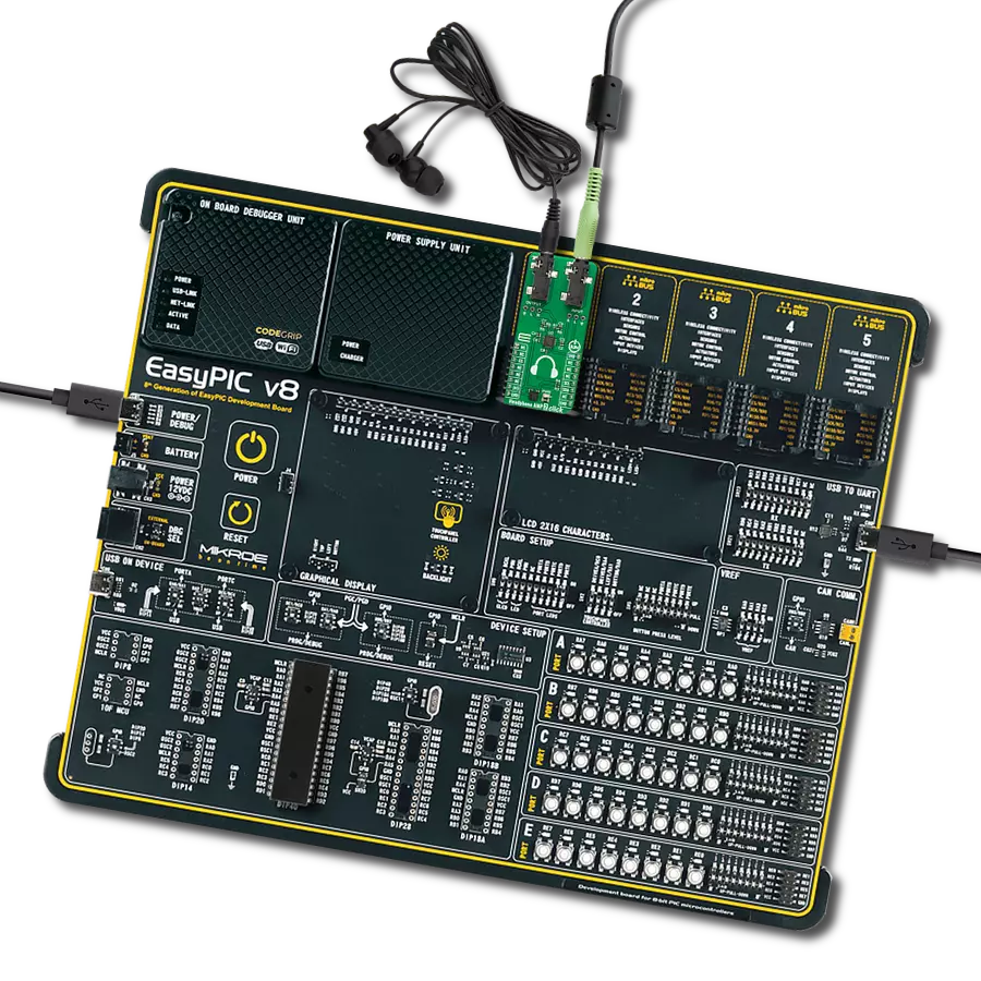
Development board
EasyAVR v7 is the seventh generation of AVR development boards specially designed for the needs of rapid development of embedded applications. It supports a wide range of 16-bit AVR microcontrollers from Microchip and has a broad set of unique functions, such as a powerful onboard mikroProg programmer and In-Circuit debugger over USB. The development board is well organized and designed so that the end-user has all the necessary elements in one place, such as switches, buttons, indicators, connectors, and others. With four different connectors for each port, EasyAVR v7 allows you to connect accessory boards, sensors, and custom electronics more
efficiently than ever. Each part of the EasyAVR v7 development board contains the components necessary for the most efficient operation of the same board. An integrated mikroProg, a fast USB 2.0 programmer with mikroICD hardware In-Circuit Debugger, offers many valuable programming/debugging options and seamless integration with the Mikroe software environment. Besides it also includes a clean and regulated power supply block for the development board. It can use a wide range of external power sources, including an external 12V power supply, 7-12V AC or 9-15V DC via DC connector/screw terminals, and a power source via the USB Type-B (USB-B)
connector. Communication options such as USB-UART and RS-232 are also included, alongside the well-established mikroBUS™ standard, three display options (7-segment, graphical, and character-based LCD), and several different DIP sockets which cover a wide range of 16-bit AVR MCUs. EasyAVR v7 is an integral part of the Mikroe ecosystem for rapid development. Natively supported by Mikroe software tools, it covers many aspects of prototyping and development thanks to a considerable number of different Click boards™ (over a thousand boards), the number of which is growing every day.

Microcontroller Overview
MCU Card / MCU

Architecture
AVR
MCU Memory (KB)
64
Silicon Vendor
Microchip
Pin count
40
RAM (Bytes)
4096
Used MCU Pins
mikroBUS™ mapper
Take a closer look
Click board™ Schematic

Step by step
Project assembly

Start by selecting your development board and Click board™. Begin with the EasyAVR v7 as your development board.


Track your results in real time
Application Output
1. Application Output - In Debug mode, the 'Application Output' window enables real-time data monitoring, offering direct insight into execution results. Ensure proper data display by configuring the environment correctly using the provided tutorial.

2. UART Terminal - Use the UART Terminal to monitor data transmission via a USB to UART converter, allowing direct communication between the Click board™ and your development system. Configure the baud rate and other serial settings according to your project's requirements to ensure proper functionality. For step-by-step setup instructions, refer to the provided tutorial.

3. Plot Output - The Plot feature offers a powerful way to visualize real-time sensor data, enabling trend analysis, debugging, and comparison of multiple data points. To set it up correctly, follow the provided tutorial, which includes a step-by-step example of using the Plot feature to display Click board™ readings. To use the Plot feature in your code, use the function: plot(*insert_graph_name*, variable_name);. This is a general format, and it is up to the user to replace 'insert_graph_name' with the actual graph name and 'variable_name' with the parameter to be displayed.

Software Support
Library Description
This library contains API for AudioAmp 3 Click driver.
Key functions:
void audioamp3_cfg_setup ( audioamp3_cfg_t *cfg )- This function power up the audio amplifierAUDIOAMP3_STATUS_T audioamp3_set_play_mode ( audioamp3_t *ctx )- This function set the play mode for all channelsAUDIOAMP3_STATUS_T audioamp3_set_gain_lvl ( audioamp3_t *ctx, uint8_t gain_lvl )- This function set the gain level for all channels
Open Source
Code example
The complete application code and a ready-to-use project are available through the NECTO Studio Package Manager for direct installation in the NECTO Studio. The application code can also be found on the MIKROE GitHub account.
/*!
 * \file
 * \brief AudioAmp3 Click example
 *
 * # Description
 * AudioAmp 3 Click is a stereo audio amplifier, capable of delivering
 * up to 79W per channel with the 4Ω load.
 *
 * The demo application is composed of two sections :
 *
 * ## Application Init
 * Application Init performs Logger and Click initialization.
 *
 * ## Application Task
 * This is an example which demonstrates the use of AudioAmp 3 click board.
 * In application task function is used that will increase volume of the sound
 * from MIN to MAX and reverse.
 * Results are being sent to the UART Terminal where you can track their changes.
 *
 * \author Mihajlo Djordjevic
 *
 */
// ------------------------------------------------------------------- INCLUDES

#include "board.h"
#include "log.h"
#include "audioamp3.h"

uint8_t cnt;
uint8_t data_out[ 10 ];
uint8_t status_flag;

// ------------------------------------------------------------------ VARIABLES

static audioamp3_t audioamp3;
static log_t logger;

// ------------------------------------------------------ APPLICATION FUNCTIONS

void application_init ( void )
{
    log_cfg_t log_cfg;
    audioamp3_cfg_t cfg;

    /**
     * Logger initialization.
     * Default baud rate: 115200
     * Default log level: LOG_LEVEL_DEBUG
     * @note If USB_UART_RX and USB_UART_TX
     * are defined as HAL_PIN_NC, you will
     * need to define them manually for log to work.
     * See @b LOG_MAP_USB_UART macro definition for detailed explanation.
     */
    LOG_MAP_USB_UART( log_cfg );
    log_init( &logger, &log_cfg );
    log_info( &logger, "---- Application Init ----" );
    Delay_ms ( 100 );

    //  Click initialization.

    audioamp3_cfg_setup( &cfg );
    AUDIOAMP3_MAP_MIKROBUS( cfg, MIKROBUS_1 );
    audioamp3_init( &audioamp3, &cfg );

    log_printf( &logger, "--------------------------\r\n\n" );
    log_printf( &logger, "--- AudioAmp  3  Click ---\r\n" );
    log_printf( &logger, "--------------------------\r\n\n" );
    Delay_ms ( 1000 );

    audioamp3_power_up( &audioamp3 );
    log_printf( &logger, "          Power Up          \r\n" );
    log_printf( &logger, " ---------------------------\r\n\n" );
    Delay_100ms();

    audioamp3_set_channel_low_to_low( &audioamp3, AUDIOAMP3_MASK_BIT_SEL_CH_1 );
    log_printf( &logger, " Set channel 1 low-low state \r\n" );
    log_printf( &logger, " ---------------------------\r\n\n" );
    Delay_100ms();

    audioamp3_set_channel_low_to_low( &audioamp3, AUDIOAMP3_MASK_BIT_SEL_CH_2 );
    log_printf( &logger, " Set channel 2 low-low state \r\n" );
    log_printf( &logger, " ---------------------------\r\n\n" );
    Delay_100ms();

    audioamp3_set_channel_mute_mode( &audioamp3, AUDIOAMP3_MASK_BIT_SEL_ALL_CH );
    log_printf( &logger, "      Mute All Channels     \r\n" );
    log_printf( &logger, " ---------------------------\r\n\n" );
    Delay_100ms();

    audioamp3_run_channel_diagnostics( &audioamp3, AUDIOAMP3_MASK_BIT_SEL_ALL_CH );
    log_printf( &logger, "       Run Diagnostics      \r\n" );
    log_printf( &logger, " ---------------------------\r\n\n" );
    Delay_100ms();

    audioamp3_hw_reset( &audioamp3 );
    log_printf( &logger, "       Hardware Reset       \r\n" );
    log_printf( &logger, " ---------------------------\r\n\n" );
    Delay_100ms();

    audioamp3_read_all_diagnostics( &audioamp3, &data_out[ 0 ] );
    log_printf( &logger, "      Read Diagnostics      \r\n" );
    log_printf( &logger, " ---------------------------\r\n\n" );
    Delay_100ms();

    log_printf( &logger, "--------------------------\r\n\n" );
    log_printf( &logger, "    Initialization  done  \r\n" );
    log_printf( &logger, "--------------------------\r\n\n" );
    Delay_ms ( 1000 );

    audioamp3_set_play_mode( &audioamp3 );
    log_printf( &logger, " ---------------------------\r\n\n" );
    log_printf( &logger, "            Play            \r\n" );
    log_printf( &logger, " ---------------------------\r\n\n" );
    Delay_100ms();
}

void application_task ( void )
{
    for ( cnt = AUDIOAMP3_GAIN_VAL_MIN; cnt < AUDIOAMP3_GAIN_VAL_5; cnt++ )
    {
        status_flag = audioamp3_set_gain_lvl( &audioamp3, cnt );
        log_printf( &logger, "    -  Volume Up  -  \r\n" );
        Delay_ms( 2000 );
    }

    log_printf( &logger, " ---------------------------\r\n\n" );

    for ( cnt = AUDIOAMP3_GAIN_VAL_MAX; cnt > AUDIOAMP3_GAIN_VAL_0; cnt-- )
    {
        status_flag = audioamp3_set_gain_lvl( &audioamp3, cnt );

        log_printf( &logger, "    -  Volume Down  -  \r\n" );
        Delay_ms( 2000 );
    }

    log_printf( &logger, " ---------------------------\r\n\n" );
}

void main ( void )
{
    application_init( );

    for ( ; ; )
    {
        application_task( );
    }
}

// ------------------------------------------------------------------------ END