Simplify temperature tracking with NCT75 and PIC32MZ1024EFH064
Monitoring the world, one degree at a time
Published Nov 08, 2023
Click board™
Thermo 15 Click
Dev. board
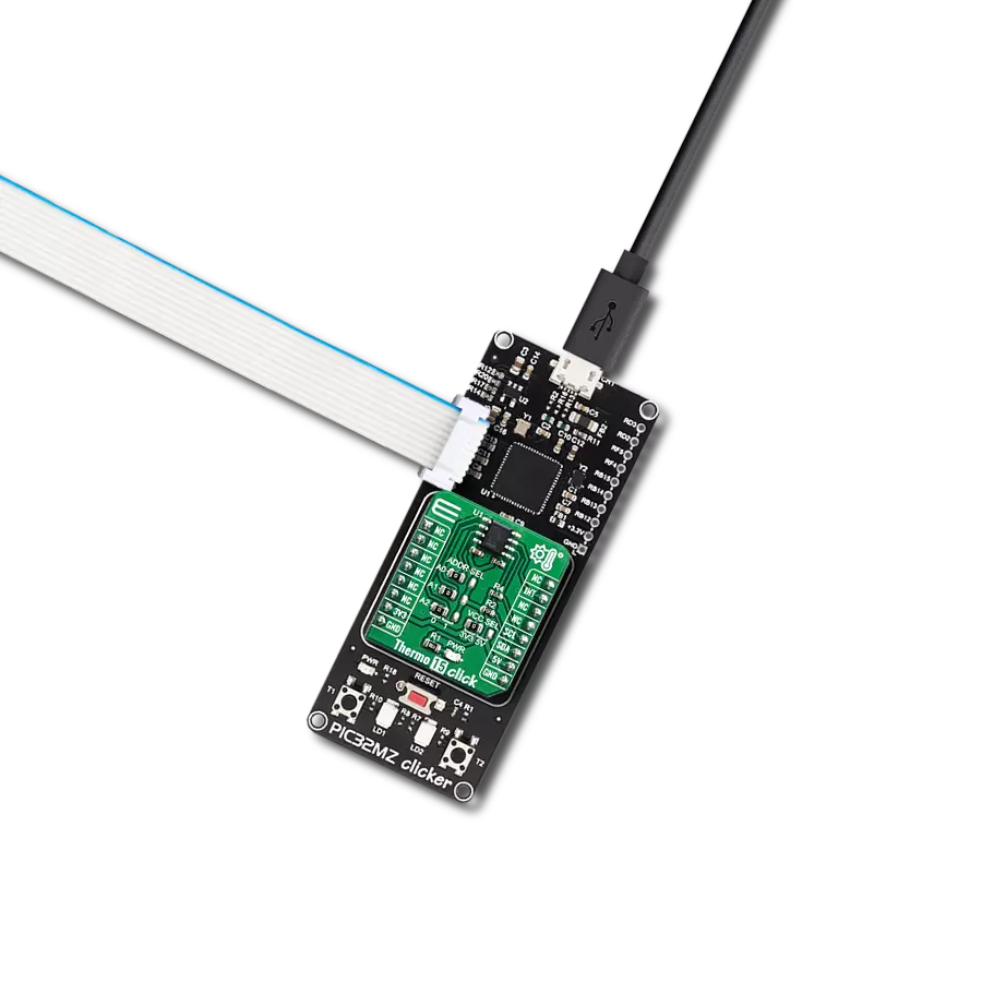
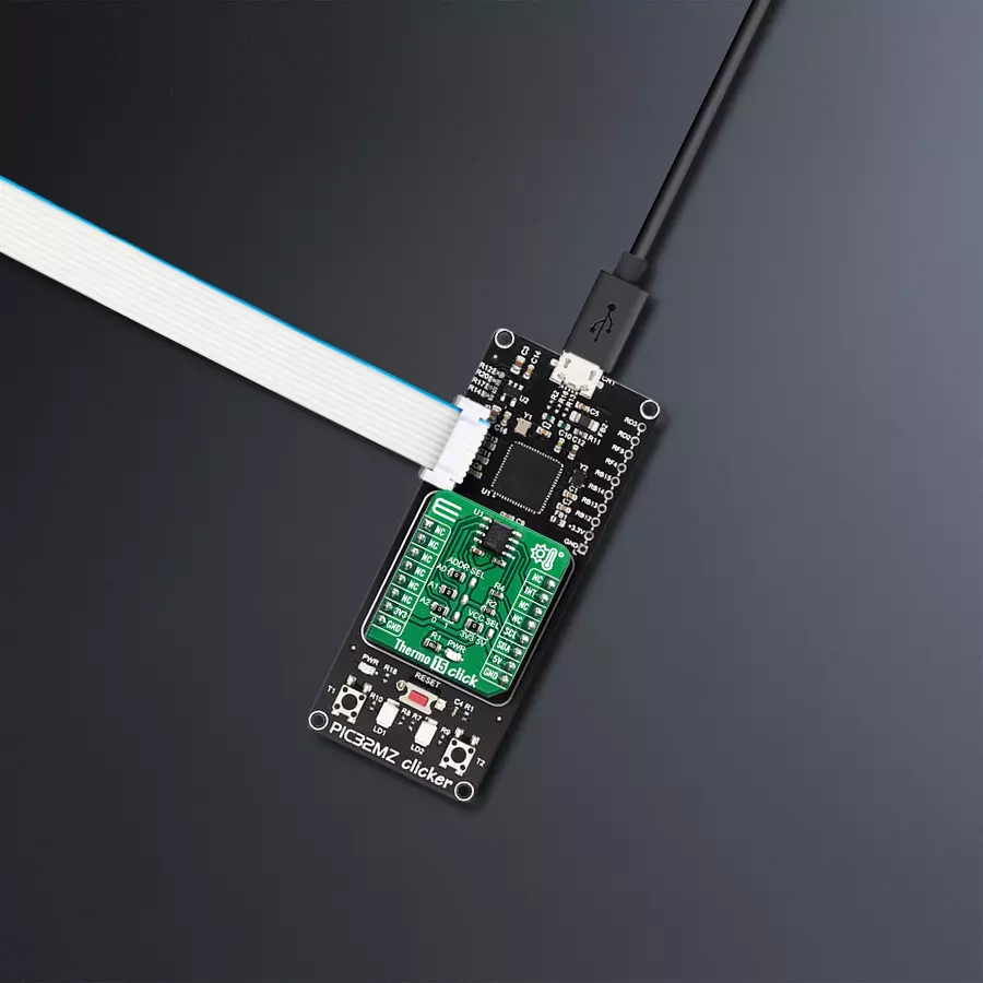
PIC32MZ clicker
Compiler
NECTO Studio
MCU
PIC32MZ1024EFH064
Experience the convenience of remote temperature monitoring and alerts, ensuring your assets are protected 24/7.
A
A
Hardware Overview
How does it work?
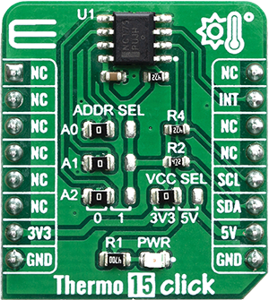
Thermo 15 Click is based on the NCT75, a high accuracy temperature sensor IC with the 2-Wire interface, from ON Semiconductor. The Click board™ itself has a reasonably small number of components because most of the measurement circuitry is already integrated on the NCT75 sensor. The I2C / SMBus compatible serial interface lines, along with the INT pin, which also works in the open drain configuration, are pulled up by the onboard resistors. The 2-Wire lines are routed to the respective I2C lines of the mikroBUS™ (SCK and SDA), while the INT pin is routed to the INT pin of the mikroBUS™. The sensor IC uses the I2C/SMBus compatible communication interface. There are six registers for configuring and reading the teperature: the address pointer register, 4 data registers and a one-shot register. The address pointer register is used to select which register is to respond to a read or write operation. The data registers are used to set the high and low temperature limits, temperature hysteresis for the interrupt events, and all the working parameters. One of the data registers is Stored Temperature as well, used to store the sampled temperature data. The measured temperature is stored in this 16-bit read only register in twos complement format with the MSB as the sign bit. More information about all the registers can be found in
the NCT75 datasheet. However, provided library contains functions that simplify the use of the Thermo 15 click. The included application example demonstrates their functionality and it can be used as a reference for custom design. An analog signal from the thermal sensor is sampled by the internal ADC converter, with the resolution of 12 bits. Thanks to high resolution ADC, the step size can be as small as 0.0625°C. If an 8 bit (1°C resolution) reading is required then a single byte read is sufficient. The INT pin is used to trigger an interrupt event on the host MCU. This pin can operate in two different modes – overtemperature mode and SMBus alert mode. Since the Click board™ features a pull-up resistor, it is advised to set the polarity so that the asserted state drives the pin to a LOW logic level. A critical temperature values are stored in the data registers. The INT pin can operate in comparator and interrupt event modes. When working in the Comparator mode, these pins will be triggered whenever a temperature limit is exceeded. The pins stays asserted until the temperature drops below the hysteresis level. Both values are set in the respective temperature registers (limit and hysteresis). This mode is useful for thermostat-like applications: it can be used to power down a system in case of overheating or turn off the cooling fan if the temperature is low enough. If set to
work in the therm mode, the INT pin will stay asserted when the temperature exceeds the value in the high limit register. When the temperature drops below the hysteresis level, the INT pin will be cleared. This mode is used to trigger an interrupt on the host MCU, which is supposed to read the sensor when the interrupt event is generated. The device can be set to work in several different power modes. It can be set to continuously sample the temperature measurements, it can be set to work in the one-shot mode, and it can be set to stay in the shutdown mode. The shutdown mode consumes the least power, keeping all the internal sections but the communication section, unpowered. The one-shot mode allows the device to stay in the shutdown mode, run a single conversion cycle on demand, and the revert back to the shutdown mode. This allows for a lower power consumption. The design of the Click board™ itself is such that the thermal radiation from other components, which might affect the environmental temperature readings of the sensor, is reduced. The onboard SMD jumper labeled as VCC SEL allows voltage selection for interfacing with both 3.3V and 5V MCUs, while the ADDR SEL jumpers allows the user to switch between different I2C addresses.

Features overview
Development board
PIC32MZ Clicker is a compact starter development board that brings the flexibility of add-on Click boards™ to your favorite microcontroller, making it a perfect starter kit for implementing your ideas. It comes with an onboard 32-bit PIC32MZ microcontroller with FPU from Microchip, a USB connector, LED indicators, buttons, a mikroProg connector, and a header for interfacing with external electronics. Thanks to its compact design with clear and easy-recognizable silkscreen markings, it provides a fluid and immersive working experience, allowing access anywhere and under
any circumstances. Each part of the PIC32MZ Clicker development kit contains the components necessary for the most efficient operation of the same board. In addition to the possibility of choosing the PIC32MZ Clicker programming method, using USB HID mikroBootloader, or through an external mikroProg connector for PIC, dsPIC, or PIC32 programmer, the Clicker board also includes a clean and regulated power supply module for the development kit. The USB Micro-B connection can provide up to 500mA of current, which is more than enough to operate all onboard
and additional modules. All communication methods that mikroBUS™ itself supports are on this board, including the well-established mikroBUS™ socket, reset button, and several buttons and LED indicators. PIC32MZ Clicker is an integral part of the Mikroe ecosystem, allowing you to create a new application in minutes. Natively supported by Mikroe software tools, it covers many aspects of prototyping thanks to a considerable number of different Click boards™ (over a thousand boards), the number of which is growing every day.

Microcontroller Overview
MCU Card / MCU

Architecture
PIC32
MCU Memory (KB)
1024
Silicon Vendor
Microchip
Pin count
64
RAM (Bytes)
524288
Used MCU Pins
mikroBUS™ mapper
Take a closer look
Click board™ Schematic

Step by step
Project assembly

Start by selecting your development board and Click board™. Begin with the PIC32MZ clicker as your development board.


Software Support
Library Description
This library contains API for Thermo 15 Click driver.
Key functions:
thermo15_get_temperature_data- Ambient temperature datathermo15_set_temp_register- Set temperature registerthermo15_get_interrupt_state- Interrupt state
Open Source
Code example
The complete application code and a ready-to-use project are available through the NECTO Studio Package Manager for direct installation in the NECTO Studio. The application code can also be found on the MIKROE GitHub account.
/*!
 * \file
 * \brief Thermo15 Click example
 *
 * # Description
 * This demo-app shows the temperature measurement procedure using Thermo 15 Click.
 *
 * The demo application is composed of two sections :
 *
 * ## Application Init
 * Configuring Clicks and log objects.
 * Setting the Click in the default configuration to start the measurement.
 *
 * ## Application Task
 * Reads ambient temperature data and this data logs to USBUART every 1500ms.
 *
 * \author Katarina Perendic
 *
 */
// ------------------------------------------------------------------- INCLUDES

#include "board.h"
#include "log.h"
#include "thermo15.h"

// ------------------------------------------------------------------ VARIABLES

static thermo15_t thermo15;
static log_t logger;

// ------------------------------------------------------ APPLICATION FUNCTIONS

void application_init ( void )
{
    log_cfg_t log_cfg;
    thermo15_cfg_t cfg;

    /**
     * Logger initialization.
     * Default baud rate: 115200
     * Default log level: LOG_LEVEL_DEBUG
     * @note If USB_UART_RX and USB_UART_TX
     * are defined as HAL_PIN_NC, you will
     * need to define them manually for log to work.
     * See @b LOG_MAP_USB_UART macro definition for detailed explanation.
     */
    LOG_MAP_USB_UART( log_cfg );
    log_init( &logger, &log_cfg );
    log_info( &logger, "---- Application Init ----" );

    //  Click initialization.

    thermo15_cfg_setup( &cfg );
    THERMO15_MAP_MIKROBUS( cfg, MIKROBUS_1 );
    thermo15_init( &thermo15, &cfg );

    thermo15_default_cfg ( &thermo15 );
    log_info( &logger, "---- Start measurement ----" );
}

void application_task ( void )
{
    float temperature;

    temperature = thermo15_get_temperature_data( &thermo15, THERMO15_TEMP_IN_CELSIUS );
    log_printf( &logger, "** Temperature: %.2f C \r\n", temperature );

    Delay_ms ( 1000 );
}

int main ( void )
{
    /* Do not remove this line or clock might not be set correctly. */
    #ifdef PREINIT_SUPPORTED
    preinit();
    #endif

    application_init( );

    for ( ; ; )
    {
        application_task( );
    }

    return 0;
}


// ------------------------------------------------------------------------ END
Additional Support
Resources
Category:Temperature & humidity


