Empower your systems with dynamic signal management through 74HC4851 and MK64FN1M0VDC12
Redefine connectivity with CMOS mux excellence

Published Aug 19, 2023
Click board™
MUX 4 Click
Dev. board
Clicker 2 for Kinetis
Compiler
NECTO Studio
MCU
MK64FN1M0VDC12
Whether it's for data acquisition, instrumentation, or beyond, this solution offers a reliable and adaptable solution for managing diverse analog pathways
A
A
Hardware Overview
How does it work?
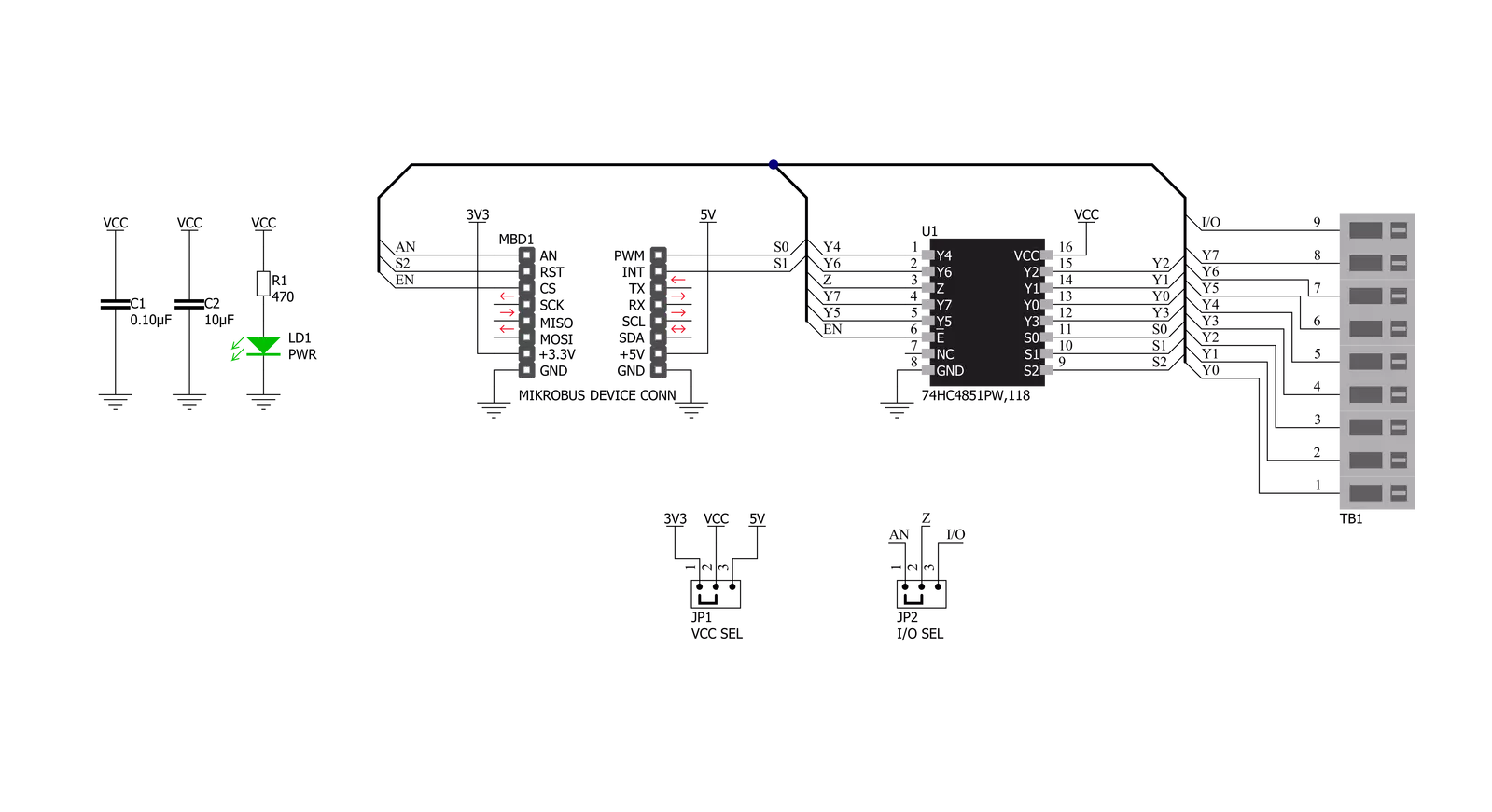
MUX 4 Click based on the 74HC4851, a precise 8-channel analog multiplexer/demultiplexer from Nexperia USA Inc. The 74HC4851 has eight independent input/output channels labeled from CH1 to CH8 that accept analog and digital signals of any voltage up to 5V. Compared to its predecessors, the 74HC4851 is better to use because it has a higher tolerance to a disturbance on channels that are not connected. The signals can travel in both directions thanks to its characteristic of being both a multiplexer and a demultiplexer. The injection-current effect control, integrated inside the 74HC4851, allows signals at disabled analog input channels to exceed the supply voltage without affecting the signal of the enabled analog channel. This feature eliminates
the need for external diode/resistor networks to keep the analog channel signals within the supply-voltage range. MUX 4 Click communicates with MCU using several GPIO pins. With the EN pin, routed to the CS pin on the mikroBUS™ socket, set to its low logic state, one of the eight switches is selected by three pins labeled as S0, S1, and S2 routed to the RST, PWM, and INT pins on the mikroBUS™ socket. With the EN pin set to its high logic state, all switches are in the high-impedance OFF state, independent of S0 to S2 pins. In addition to its eight independent input/output pins, the 74HC4851 also has a common input/output pin where it is possible to select the signal input to a given pin, more precisely, whether the signal will be brought
externally from the terminal labeled as I/O or from mikroBUS™ socket AN pin. Selection can be performed by onboard SMD jumper labeled as I/O SEL to an appropriate position marked as AN and EXT. The MUX 4 Click has one nine-position spring terminal for all input/output signals, making all wire connections reliable and straightforward. This Click board™ can operate with either 3.3V or 5V logic voltage levels selected via the VCC SEL jumper. This way, both 3.3V and 5V capable MCUs can use the communication lines properly. Also, this Click board™ comes equipped with a library containing easy-to-use functions and an example code that can be used, as a reference, for further development.


Features overview
Development board
Clicker 2 for Kinetis is a compact starter development board that brings the flexibility of add-on Click boards™ to your favorite microcontroller, making it a perfect starter kit for implementing your ideas. It comes with an onboard 32-bit ARM Cortex-M4F microcontroller, the MK64FN1M0VDC12 from NXP Semiconductors, two mikroBUS™ sockets for Click board™ connectivity, a USB connector, LED indicators, buttons, a JTAG programmer connector, and two 26-pin headers for interfacing with external electronics. Its compact design with clear and easily recognizable silkscreen markings allows you to build gadgets with unique functionalities and
features quickly. Each part of the Clicker 2 for Kinetis development kit contains the components necessary for the most efficient operation of the same board. In addition to the possibility of choosing the Clicker 2 for Kinetis programming method, using a USB HID mikroBootloader or an external mikroProg connector for Kinetis programmer, the Clicker 2 board also includes a clean and regulated power supply module for the development kit. It provides two ways of board-powering; through the USB Micro-B cable, where onboard voltage regulators provide the appropriate voltage levels to each component on the board, or
using a Li-Polymer battery via an onboard battery connector. All communication methods that mikroBUS™ itself supports are on this board, including the well-established mikroBUS™ socket, reset button, and several user-configurable buttons and LED indicators. Clicker 2 for Kinetis is an integral part of the Mikroe ecosystem, allowing you to create a new application in minutes. Natively supported by Mikroe software tools, it covers many aspects of prototyping thanks to a considerable number of different Click boards™ (over a thousand boards), the number of which is growing every day.

Microcontroller Overview
MCU Card / MCU

Architecture
ARM Cortex-M4
MCU Memory (KB)
1024
Silicon Vendor
NXP
Pin count
121
RAM (Bytes)
262144
Used MCU Pins
mikroBUS™ mapper
Take a closer look
Click board™ Schematic
Step by step
Project assembly

Start by selecting your development board and Click board™. Begin with the Clicker 2 for Kinetis as your development board.


Software Support
Library Description
This library contains API for MUX 4 Click driver.
Key functions:
mux4_read_an_pin_voltage- This function reads results of AD conversion of the AN pin and converts them to proportional voltage levelmux4_enable_input- This function enable or disables analog inputsmux4_select_input- This function selects which input channel signal is being forwarded to the AN/EXT pin
Open Source
Code example
The complete application code and a ready-to-use project are available through the NECTO Studio Package Manager for direct installation in the NECTO Studio. The application code can also be found on the MIKROE GitHub account.
/*!
 * @file main.c
 * @brief MUX 4 Click Example.
 *
 * # Description
 * This example demonstrates the use of MUX 4 Click board.
 *
 * The demo application is composed of two sections :
 *
 * ## Application Init
 * Initializes the driver and enables analog inputs.
 *
 * ## Application Task
 * Reads the voltage from all input channels and displays the values of
 * each channel on the USB UART approximately every second.
 *
 * @author Stefan Filipovic
 *
 */

#include "board.h"
#include "log.h"
#include "mux4.h"

static mux4_t mux4;       /**< MUX 4 Click driver object. */
static log_t logger;      /**< Logger object. */

void application_init ( void )
{
    log_cfg_t log_cfg;    /**< Logger config object. */
    mux4_cfg_t mux4_cfg;  /**< Click config object. */

    /**
     * Logger initialization.
     * Default baud rate: 115200
     * Default log level: LOG_LEVEL_DEBUG
     * @note If USB_UART_RX and USB_UART_TX
     * are defined as HAL_PIN_NC, you will
     * need to define them manually for log to work.
     * See @b LOG_MAP_USB_UART macro definition for detailed explanation.
     */
    LOG_MAP_USB_UART( log_cfg );
    log_init( &logger, &log_cfg );
    Delay_ms ( 100 );
    log_info( &logger, " Application Init " );

    // Click initialization.

    mux4_cfg_setup( &mux4_cfg );
    MUX4_MAP_MIKROBUS( mux4_cfg, MIKROBUS_1 );
    if ( ADC_ERROR == mux4_init( &mux4, &mux4_cfg ) )
    {
        log_error( &logger, " Application Init Error. " );
        log_info( &logger, " Please, run program again... " );

        for ( ; ; );
    }

    mux4_enable_input( &mux4, MUX4_ENABLE_INPUT );
}

void application_task ( void )
{
    float mux4_an_voltage = 0;

    for ( uint8_t cnt = MUX4_SELECT_INPUT_1; cnt <= MUX4_SELECT_INPUT_8; cnt++ )
    {
        mux4_select_input( &mux4, cnt );
        Delay_ms ( 10 );
        if ( ADC_ERROR != mux4_read_an_pin_voltage ( &mux4, &mux4_an_voltage ) )
        {
            log_printf( &logger, " CH%u Voltage : %.3f V\r\n", ( uint16_t ) cnt, mux4_an_voltage );
        }
    }
    log_printf( &logger, " ----------------------------\r\n" );
    Delay_ms ( 1000 );
}

int main ( void )
{
    /* Do not remove this line or clock might not be set correctly. */
    #ifdef PREINIT_SUPPORTED
    preinit();
    #endif

    application_init( );

    for ( ; ; )
    {
        application_task( );
    }

    return 0;
}

// ------------------------------------------------------------------------ END


