Enhance your industrial processes with ADS1247 and MK64FN1M0VDC12
RTDs - The path to temperature excellence
Published Nov 11, 2023
Click board™
RTD 2 Click
Dev. board
Clicker 2 for Kinetis
Compiler
NECTO Studio
MCU
MK64FN1M0VDC12
Discover how our RTD solution can provide you with accurate and reliable temperature measurements for your critical processes.
A
A
Hardware Overview
How does it work?
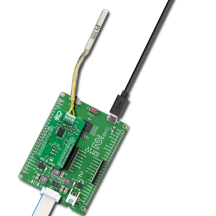
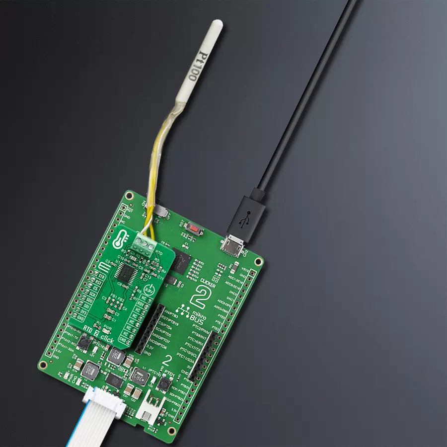
RTD 2 Click is based on the ADS1247, a highly integrated 24-bit data converter with a programmable gain amplifier (PGA) for sensor measurement applications from Texas Instruments. The ADS1247 includes a delta-sigma (ΔΣ) ADC with an adjustable single-cycle settling digital filter, an internal oscillator, and an SPI-compatible serial interface. It also has a flexible input multiplexer with system monitoring capability and general-purpose I/O settings, a very low-drift voltage reference, and two matched current sources for sensor excitation. The ADS1247 provides a system monitor function. This function can measure the analog power supply, digital power supply, external voltage reference, or ambient temperature. Note that the system monitor function provides a coarse result. When the system monitor is enabled, the analog inputs are disconnected. The two IDAC current sources integrated into the ADS1247 are used to implement the lead-wire compensation. One IDAC current source (IDAC1) provides excitation to the RTD element. The other current source (IDAC2)
has the same current setting, which cancels lead-wire resistance by generating a voltage drop across lead-wire resistance R2 equal to the voltage drop across the R1 resistor (9.09k). Because the voltage across the RTD is measured differentially at ADC pins AIN1 and AIN2 of the ADS1247, the voltages across the lead-wire resistances cancel. The ADC reference voltage (pins REFP0 and REFN0) is derived from the voltage across the R5 resistor with the currents from IDAC1 and IDAC2, providing ratiometric cancellation of current-source drift. R5 also level shifts the RTD signal to within the ADC-specified common-mode input range. The RTD 2 Click communicates with MCU using the standard SPI serial interface with an additional data-ready signal routed on the INT pin of the mikroBUS™ socket labeled as RDY. Data Ready signal indicates when a new conversion is complete, and the conversion result is stored in the conversion result buffer. It also has an active-low Reset signal routed on the RST pin of the mikroBUS™ used to reset the device and a precise conversion control signal routed on the AN pin of
the mikroBUS™ socket labeled as STR. The ADS1247 stays in Reset Mode as long as the RST pin stays low. When the RST pin goes high, the ADC comes out of Reset Mode and can convert data. This Click board™ can work only with 3-wire probe types that MIKROE offers, such as the PT100 type Platinum Probe, an RTD probe used to measure temperatures up to 250°C. Platinum is an excellent choice since they are very stable and reusable and are resistant to corrosion or oxidation. The measurement probe is connected to the RTD 2 Click by using the screw terminal on the top of the board, and it has wires that can be 1m long, which makes it possible to measure high temperatures from a safe distance. This Click board™ can be operated only with a 3.3V logic voltage level. The board must perform appropriate logic voltage level conversion before using MCUs with different logic levels. Also, it comes equipped with a library containing functions and an example code that can be used as a reference for further development.

Features overview
Development board
Clicker 2 for Kinetis is a compact starter development board that brings the flexibility of add-on Click boards™ to your favorite microcontroller, making it a perfect starter kit for implementing your ideas. It comes with an onboard 32-bit ARM Cortex-M4F microcontroller, the MK64FN1M0VDC12 from NXP Semiconductors, two mikroBUS™ sockets for Click board™ connectivity, a USB connector, LED indicators, buttons, a JTAG programmer connector, and two 26-pin headers for interfacing with external electronics. Its compact design with clear and easily recognizable silkscreen markings allows you to build gadgets with unique functionalities and
features quickly. Each part of the Clicker 2 for Kinetis development kit contains the components necessary for the most efficient operation of the same board. In addition to the possibility of choosing the Clicker 2 for Kinetis programming method, using a USB HID mikroBootloader or an external mikroProg connector for Kinetis programmer, the Clicker 2 board also includes a clean and regulated power supply module for the development kit. It provides two ways of board-powering; through the USB Micro-B cable, where onboard voltage regulators provide the appropriate voltage levels to each component on the board, or
using a Li-Polymer battery via an onboard battery connector. All communication methods that mikroBUS™ itself supports are on this board, including the well-established mikroBUS™ socket, reset button, and several user-configurable buttons and LED indicators. Clicker 2 for Kinetis is an integral part of the Mikroe ecosystem, allowing you to create a new application in minutes. Natively supported by Mikroe software tools, it covers many aspects of prototyping thanks to a considerable number of different Click boards™ (over a thousand boards), the number of which is growing every day.

Microcontroller Overview
MCU Card / MCU

Architecture
ARM Cortex-M4
MCU Memory (KB)
1024
Silicon Vendor
NXP
Pin count
121
RAM (Bytes)
262144
You complete me!
Accessories
The PT100 3-wire temperature probe is an advanced RTD platinum sensor designed for precise temperature measurement up to 250°C. Perfectly compatible with the RTD Click board™, this probe utilizes RTD sensors - thermosensitive resistors that adapt their resistance to temperature changes. The probe's core features a meticulously crafted strip of platinum with a resistance of 100Ω at 0°C, earning the designation PT100. Key features include a temperature range of up to 250⁰ Celsius, a 3-wire configuration for enhanced accuracy, a length of 1m (100cm, 3.37 inches), Grade 2B construction for durability, and a tight tolerance of 0.5". Whether in industrial or scientific settings, the PT100 3-wire temperature probe delivers reliable and precise temperature readings, ensuring optimal performance in diverse applications.

Used MCU Pins
mikroBUS™ mapper
Take a closer look
Click board™ Schematic

Step by step
Project assembly

Start by selecting your development board and Click board™. Begin with the Clicker 2 for Kinetis as your development board.


Software Support
Library Description
This library contains API for RTD 2 Click driver.
Key functions:
rtd2_check_new_data_ready- The function check new data readyrtd2_get_temperature- The function read output data and return ambient temperature from the PT100 3-wire temperature probertd2_enable_start- The function enables ADC conversion
Open Source
Code example
The complete application code and a ready-to-use project are available through the NECTO Studio Package Manager for direct installation in the NECTO Studio. The application code can also be found on the MIKROE GitHub account.
/*!
 * \file
 * \brief Rtd 2 Click example
 *
 * # Description
 * RTD 2 Click board is commonly used for measuring ambient temperature
 * from the PT100 3-wire temperature probe.
 *
 * The demo application is composed of two sections :
 *
 * ## Application Init
 * Initializes the driver, performs a hardware reset, and sets the Click
 * default configuration.
 *
 * ## Application Task
 * Reads an ambient temperature measured by the PT100 3-wire temperature probe
 * connected to the RTD 2 Click board, and logs the results on the USB UART each second.
 *
 * \author MikroE Team
 *
 */
// ------------------------------------------------------------------- INCLUDES

#include "board.h"
#include "log.h"
#include "rtd2.h"

// ------------------------------------------------------------------ VARIABLES

static rtd2_t rtd2;
static log_t logger;
static float temperature;

// ------------------------------------------------------ APPLICATION FUNCTIONS

void application_init ( void )
{
    log_cfg_t log_cfg;
    rtd2_cfg_t cfg;

    /**
     * Logger initialization.
     * Default baud rate: 115200
     * Default log level: LOG_LEVEL_DEBUG
     * @note If USB_UART_RX and USB_UART_TX
     * are defined as HAL_PIN_NC, you will
     * need to define them manually for log to work.
     * See @b LOG_MAP_USB_UART macro definition for detailed explanation.
     */
    LOG_MAP_USB_UART( log_cfg );
    log_init( &logger, &log_cfg );
    log_info( &logger, "---- Application Init ----" );

    //  Click initialization.
    rtd2_cfg_setup( &cfg );
    RTD2_MAP_MIKROBUS( cfg, MIKROBUS_1 );
    rtd2_init( &rtd2, &cfg );
    Delay_ms ( 200 );

    log_printf( &logger, "----- Hardware Reset ------\r\n" );
    rtd2_hw_reset( &rtd2 );
    Delay_ms ( 100 );

    log_printf( &logger, "-- Default configuration --\r\n" );
    rtd2_default_cfg( &rtd2 );
    Delay_ms ( 1000 );

    log_printf( &logger, "--------------------------\r\n" );
    log_printf( &logger, "     Start Measurement    \r\n" );
    log_printf( &logger, "--------------------------\r\n" );
    Delay_ms ( 100 );
}

void application_task ( void )
{
    if ( rtd2_check_new_data_ready( &rtd2 ) == RTD2_NEW_DATA_IS_READY )
    {
        temperature = rtd2_get_temperature( &rtd2 );
        log_printf( &logger, " Temperature : %.2f C\r\n", temperature );
        log_printf( &logger, "--------------------------\r\n");
        Delay_ms ( 1000 );
    }
    else
    {
        rtd2_enable_start( &rtd2, RTD2_START_CONVERSION_DISABLE );
        Delay_ms ( 1000 );
    }
}

int main ( void )
{
    /* Do not remove this line or clock might not be set correctly. */
    #ifdef PREINIT_SUPPORTED
    preinit();
    #endif

    application_init( );

    for ( ; ; )
    {
        application_task( );
    }

    return 0;
}


// ------------------------------------------------------------------------ END
Additional Support
Resources
Category:Temperature & humidity


