Experience the future of climate control with SHT31-DIS and STM32F415ZG
Climate control, simplified.

Published Nov 02, 2023
Click board™
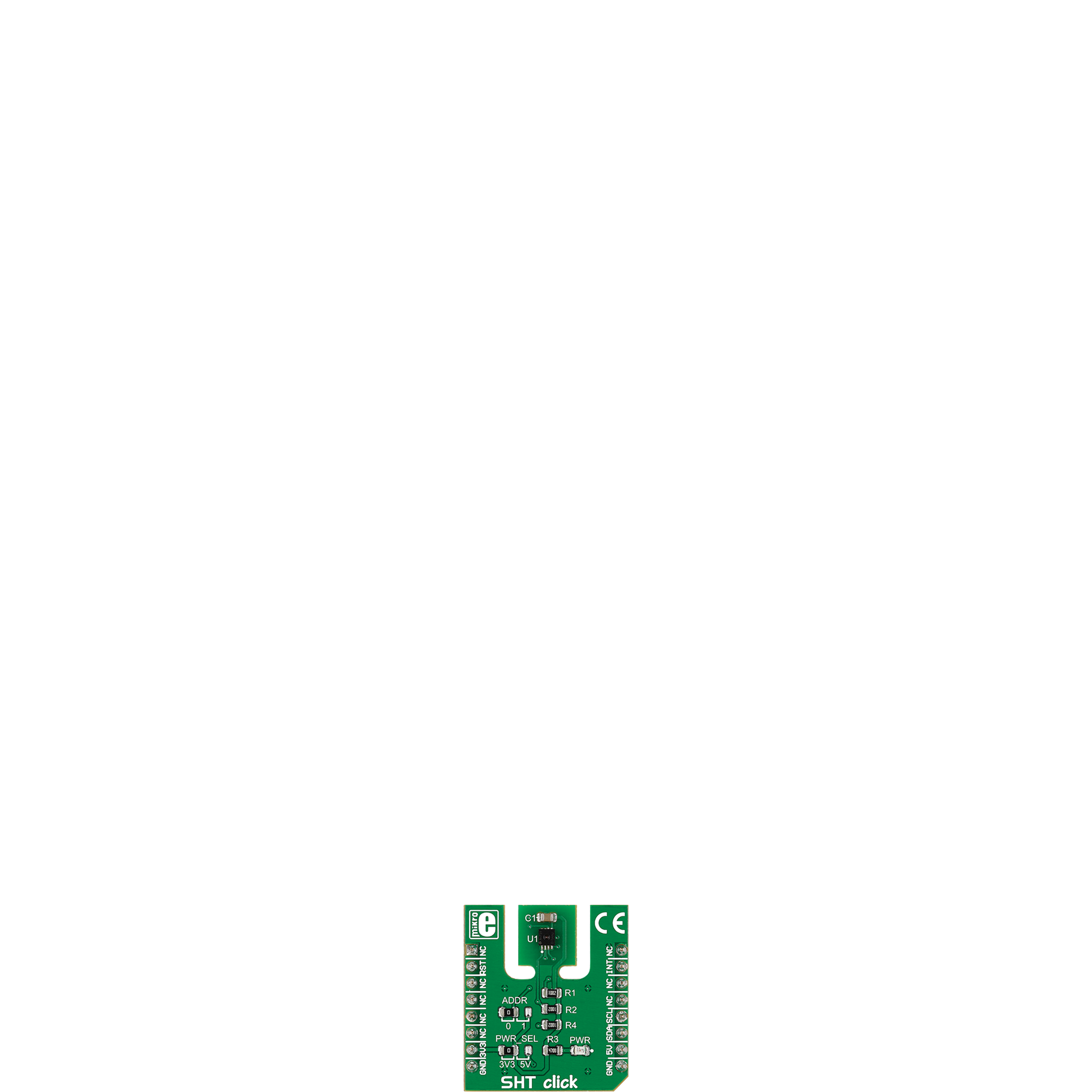
SHT Click
Dev. board
UNI Clicker
Compiler
NECTO Studio
MCU
STM32F415ZG
Our temperature and humidity sensing solution combines cutting-edge precision with unparalleled comfort, ensuring the perfect environment for your well-being
A
A
Hardware Overview
How does it work?
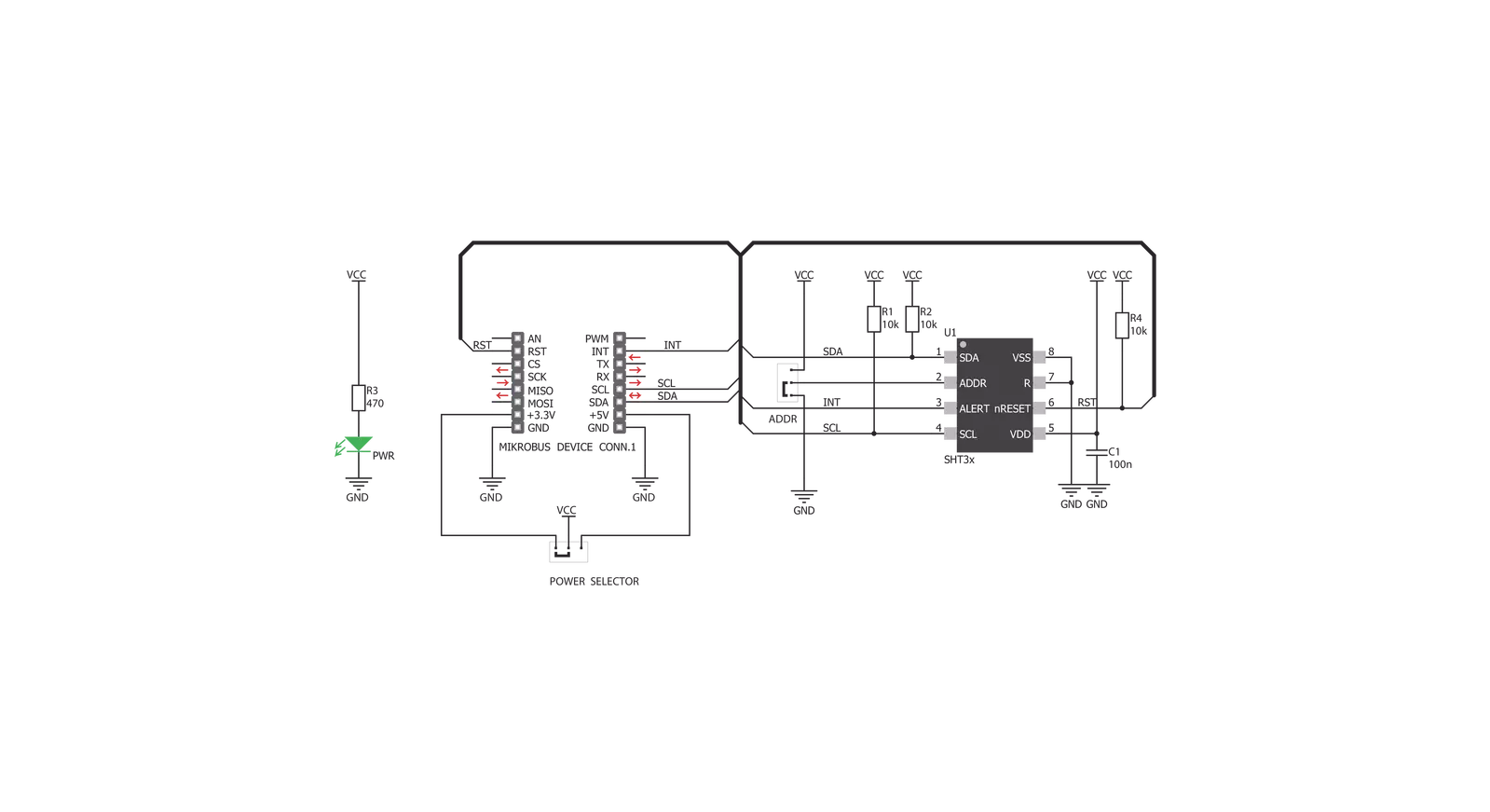
SHT Click is based on the SHT31-DIS, a humidity and temperature sensor from Sensirion. The SHT31-DIS is a robust and reliable sensor, and even when exposed to conditions outside its normal range, it can recalibrate itself once conditions stabilize. The sensor performs best when operated within the recommended normal temperature and humidity range of 5°C up to 60°C and 20%RH up to 80%RH, respectively. Long-term exposure to conditions outside the normal range, especially at high humidity, may temporarily offset the RH signal. After returning to the normal temperature
and humidity range, the sensor will slowly return to a calibration state by itself. Also, note that prolonged exposure to extreme conditions may accelerate aging. The SHT Click communicates with the host MCU using an I2C interface over the mikroBUS™ socket, with communication speeds of up to 1MHz. This Click board™ allows the selection of one of two available I2C addresses via the ADDR jumper, where I2C address 0 is selected by default. To reset the SHT31-DIS sensor, there is an RST pin with an active LOW state. The SHT31-DIS also features alert functions and can send
interrupt signals over the INT pin of the mikroBUS™ socket. The output of this pin depends on the RH/T reading relative to programmable limits. This Click board™ can operate with either 3.3V or 5V logic voltage levels selected via the PWR SEL jumper. This way, both 3.3V and 5V capable MCUs can use the communication lines properly. Also, this Click board™ comes equipped with a library containing easy-to-use functions and an example code that can be used as a reference for further development.

Features overview
Development board
UNI Clicker is a compact development board designed as a complete solution that brings the flexibility of add-on Click boards™ to your favorite microcontroller, making it a perfect starter kit for implementing your ideas. It supports a wide range of microcontrollers, such as different ARM, PIC32, dsPIC, PIC, and AVR from various vendors like Microchip, ST, NXP, and TI (regardless of their number of pins), four mikroBUS™ sockets for Click board™ connectivity, a USB connector, LED indicators, buttons, a debugger/programmer connector, and two 26-pin headers for interfacing with external electronics. Thanks to innovative manufacturing technology, it allows you to build
gadgets with unique functionalities and features quickly. Each part of the UNI Clicker development kit contains the components necessary for the most efficient operation of the same board. In addition to the possibility of choosing the UNI Clicker programming method, using a third-party programmer or CODEGRIP/mikroProg connected to onboard JTAG/SWD header, the UNI Clicker board also includes a clean and regulated power supply module for the development kit. It provides two ways of board-powering; through the USB Type-C (USB-C) connector, where onboard voltage regulators provide the appropriate voltage levels to each component on the board, or using a Li-Po/Li
Ion battery via an onboard battery connector. All communication methods that mikroBUS™ itself supports are on this board (plus USB HOST/DEVICE), including the well-established mikroBUS™ socket, a standardized socket for the MCU card (SiBRAIN standard), and several user-configurable buttons and LED indicators. UNI Clicker is an integral part of the Mikroe ecosystem, allowing you to create a new application in minutes. Natively supported by Mikroe software tools, it covers many aspects of prototyping thanks to a considerable number of different Click boards™ (over a thousand boards), the number of which is growing every day.

Microcontroller Overview
MCU Card / MCU
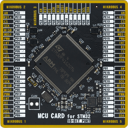
Type
8th Generation
Architecture
ARM Cortex-M4
MCU Memory (KB)
1024
Silicon Vendor
STMicroelectronics
Pin count
144
RAM (Bytes)
196608
Used MCU Pins
mikroBUS™ mapper
Take a closer look
Click board™ Schematic
Step by step
Project assembly

Start by selecting your development board and Click board™. Begin with the UNI Clicker as your development board.


Software Support
Library Description
This library contains API for SHT Click driver.
Key functions:
sht_temp_ss- Returns temperature measurement in single shot mode.sht_hum_ss- Returns humidity measurement in single shot mode.sht_heater_control- Sets the heater state.
Open Source
Code example
The complete application code and a ready-to-use project are available through the NECTO Studio Package Manager for direct installation in the NECTO Studio. The application code can also be found on the MIKROE GitHub account.
/*!
 * \file
 * \brief Sht Click example
 *
 * # Description
 * This application enables usage of the temperature and humidity sensor.
 *
 * The demo application is composed of two sections :
 *
 * ## Application Init
 * Initialize the communication interface and configure the Click board.
 *
 * ## Application Task
 * Temperature and humidity data is measured and read from the sensor.
 * After the data has been read it is displayed on the serial port.
 *
 * \author MikroE Team
 *
 */
// ------------------------------------------------------------------- INCLUDES

#include "board.h"
#include "log.h"
#include "sht.h"

// ------------------------------------------------------------------ VARIABLES

static sht_t sht;
static log_t logger;

// ------------------------------------------------------ APPLICATION FUNCTIONS

void application_init ( void )
{
    log_cfg_t log_cfg;
    sht_cfg_t cfg;

    /**
     * Logger initialization.
     * Default baud rate: 115200
     * Default log level: LOG_LEVEL_DEBUG
     * @note If USB_UART_RX and USB_UART_TX
     * are defined as HAL_PIN_NC, you will
     * need to define them manually for log to work.
     * See @b LOG_MAP_USB_UART macro definition for detailed explanation.
     */
    LOG_MAP_USB_UART( log_cfg );
    log_init( &logger, &log_cfg );
    log_info( &logger, " Application Init " );

    //  Click initialization.
    sht_cfg_setup( &cfg );
    SHT_MAP_MIKROBUS( cfg, MIKROBUS_1 );
    sht_init( &sht, &cfg );

    sht_reset( &sht );
    sht_hw_reset( &sht );
    Delay_ms ( 1000 );
    Delay_ms ( 1000 );

    log_info( &logger, " Application Task " );
}

void application_task ( void )
{
    float temperature = 0;
    float humidity = 0;

    temperature = sht_temp_ss( &sht );
    log_printf( &logger, " Temperature: %.2f degC\r\n", temperature );

    humidity = sht_hum_ss( &sht );
    log_printf( &logger, " Humidity: %.2f %%\r\n\n", humidity );

    Delay_ms ( 1000 );
}

int main ( void )
{
    /* Do not remove this line or clock might not be set correctly. */
    #ifdef PREINIT_SUPPORTED
    preinit();
    #endif

    application_init( );

    for ( ; ; )
    {
        application_task( );
    }

    return 0;
}


// ------------------------------------------------------------------------ END


