Stay on top of temperature fluctuations with BH1900NUX and PIC32MZ2048EFH100
The temperature solution you can trust
Published Nov 08, 2023
Click board™
Thermo 13 Click
Dev. board
Flip&Click PIC32MZ
Compiler
NECTO Studio
MCU
PIC32MZ2048EFH100
Discover how our temperature measurement solution can help you address temperature challenges and enhance your competitive edge
A
A
Hardware Overview
How does it work?
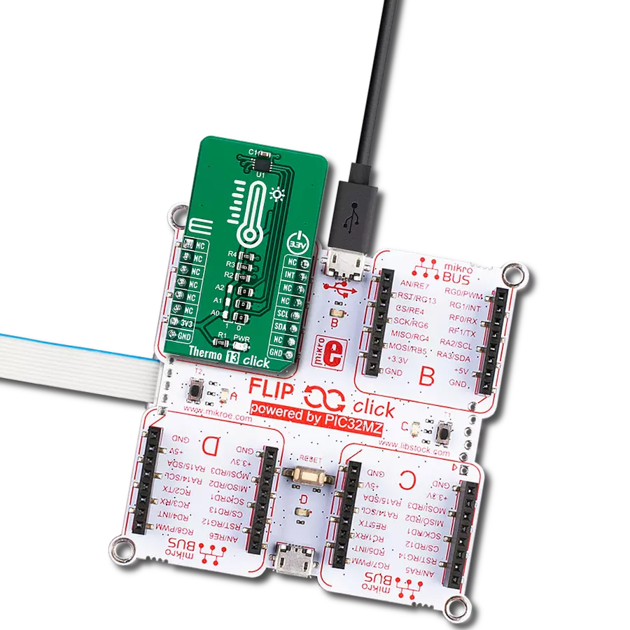
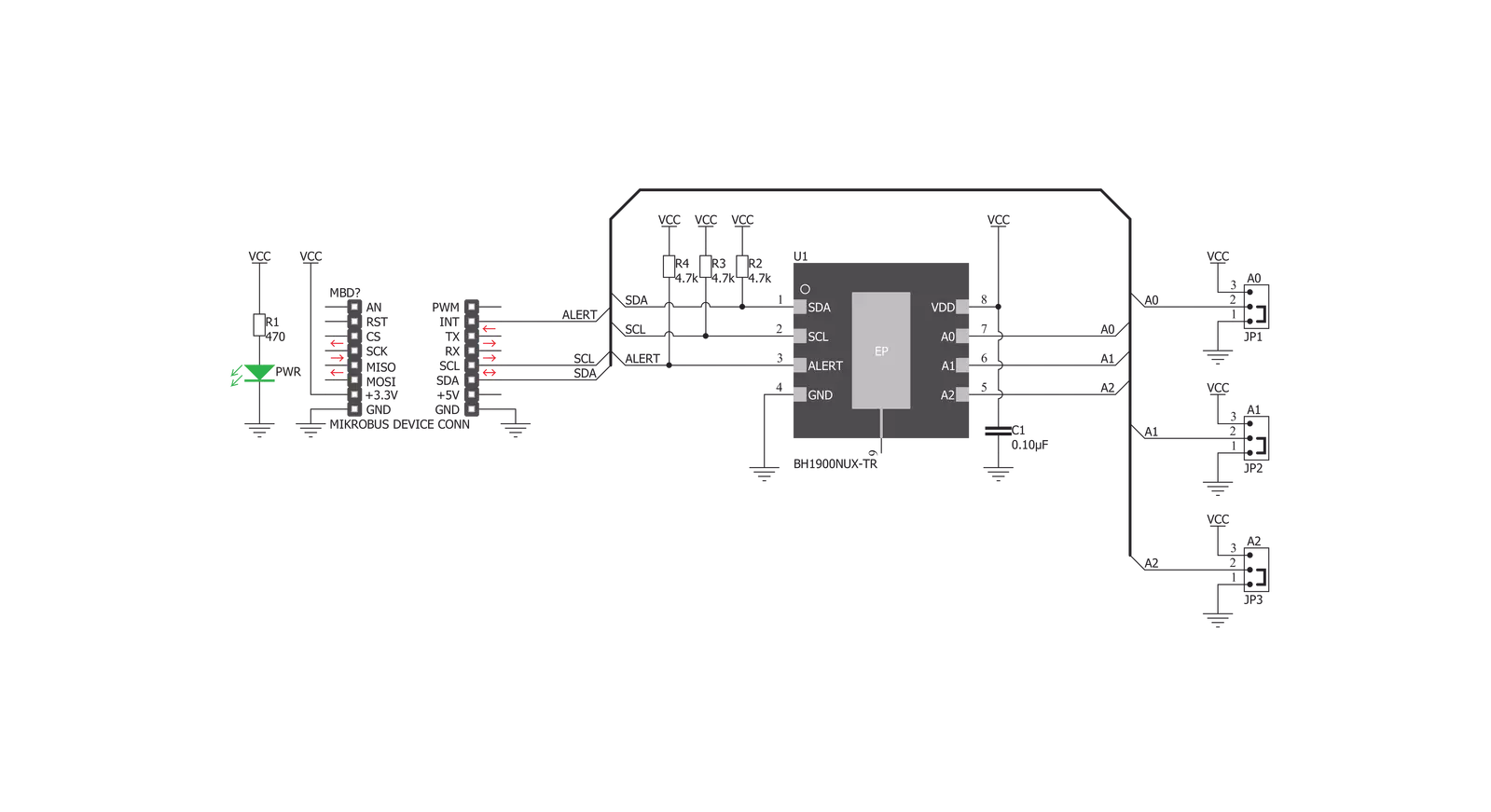
Thermo 13 Click is based on the BH1900NUX, a high accuracy temperature sensor IC with the 2-Wire interface, from ROHM Semiconductor. The Click board™ itself has a reasonably small number of components because most of the measurement circuitry is already integrated on the BH1900NUX sensor. The I2C compatible serial interface lines, along with the INT pin, which also works in the open drain configuration, are pulled up by the onboard resistors. The 2-Wire lines are routed to the respective I2C lines of the mikroBUS™ (SCK and SDA), while the ALERT pin of the sensor IC is routed to the INT pin of the mikroBUS™. The sensor IC uses the I2C compatible communication interface. There are five registers, used to set the high and low temperature limits, temperature hysteresis for the interrupt events, configuration register used to store all the working parameters, read-only register which holds the sampled temperature data, and more. More information about all the registers can be found in the BH1900NUX datasheet. However, provided library contains functions that simplify the use of the Thermo 13 click. The included application example demonstrates their functionality and it can be used as a reference for custom design. An analog signal from the thermal sensor is sampled by the internal ADC converter. Thanks to high
resolution ADC, the step size can be as small as 0.0625°C. The INT pin is used to trigger an interrupt event on the host MCU. This pin has a programmable polarity: it can be set to be asserted either to a HIGH logic level or to a LOW logic level by setting POL bit in the configuration register. Since the Click board™ features a pull-up resistor, it is advised to set the polarity so that the asserted state drives the pin to a LOW logic level. A special mechanism is employed to reduce false ALERT triggering. This mechanism includes queueing of the cycles in which the temperature limit is exceeded The ALERT pin can be set to work in two different modes: Comparator mode and thermostat mode. When working in the Comparator mode, this pin will be triggered whenever a temperature limit is exceeded. The INT pin stays asserted until the temperature drops below the hysteresis level. Both values are set in the respective temperature registers (limit and hysteresis). This mode is useful for thermostat-like applications: it can be used to power down a system in case of overheating or turn off the cooling fan if the temperature is low enough. If set to work in the thermostat mode, the INT pin will stay asserted when the temperature exceeds the value in the high limit register. When the temperature drops below the hysteresis level, the INT pin will be cleared. This mode is
used to trigger an interrupt on the host MCU, which is supposed to read the sensor when the interrupt event is generated. The device can be set to work in several different power modes. It can be set to continuously sample the temperature measurements, it can be set to the shutdown mode. The shutdown mode consumes the least power, keeping all the internal sections but the communication section, unpowered. This allows for a lower power consumption. The design of the Click board™ itself is such that the thermal radiation from other components, which might affect the environmental temperature readings of the sensor, is reduced. The onboard SMD jumper labeled as VCC SEL allows voltage selection for interfacing with both 3.3V and 5V MCUs. Thermo 13 click supports I2C communication interface, allowing it to be used with a wide range of different MCUs. The slave I2C address can be configured by an SMD jumpers, labeled as A0, A1 and A2. They are used to set the last three bis of the I2C address. This Click Board™ is designed to be operated only with up to 3.3V logic levels. Proper conversion of logic voltage levels should be applied, before the Click board™ is used with MCUs operated at 5V.

Features overview
Development board
Flip&Click PIC32MZ is a compact development board designed as a complete solution that brings the flexibility of add-on Click boards™ to your favorite microcontroller, making it a perfect starter kit for implementing your ideas. It comes with an onboard 32-bit PIC32MZ microcontroller, the PIC32MZ2048EFH100 from Microchip, four mikroBUS™ sockets for Click board™ connectivity, two USB connectors, LED indicators, buttons, debugger/programmer connectors, and two headers compatible with Arduino-UNO pinout. Thanks to innovative manufacturing technology,
it allows you to build gadgets with unique functionalities and features quickly. Each part of the Flip&Click PIC32MZ development kit contains the components necessary for the most efficient operation of the same board. In addition, there is the possibility of choosing the Flip&Click PIC32MZ programming method, using the chipKIT bootloader (Arduino-style development environment) or our USB HID bootloader using mikroC, mikroBasic, and mikroPascal for PIC32. This kit includes a clean and regulated power supply block through the USB Type-C (USB-C) connector. All communication
methods that mikroBUS™ itself supports are on this board, including the well-established mikroBUS™ socket, user-configurable buttons, and LED indicators. Flip&Click PIC32MZ development kit allows you to create a new application in minutes. Natively supported by Mikroe software tools, it covers many aspects of prototyping thanks to a considerable number of different Click boards™ (over a thousand boards), the number of which is growing every day.

Microcontroller Overview
MCU Card / MCU

Architecture
PIC32
MCU Memory (KB)
2048
Silicon Vendor
Microchip
Pin count
100
RAM (Bytes)
524288
Used MCU Pins
mikroBUS™ mapper
Take a closer look
Click board™ Schematic
Step by step
Project assembly

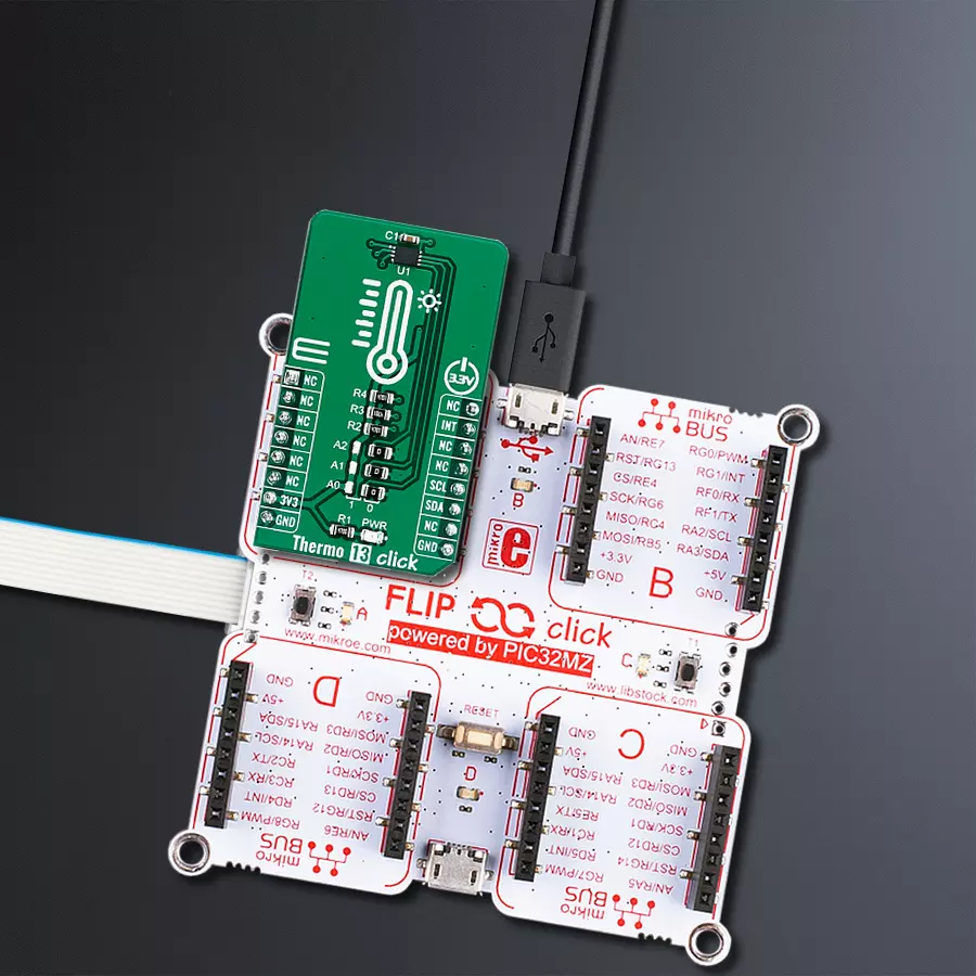
Start by selecting your development board and Click board™. Begin with the Flip&Click PIC32MZ as your development board.


Software Support
Library Description
This library contains API for Thermo 13 Click driver.
Key functions:
thermo13_set_temp_limit- Set temperature limit registerthermo13_get_temp_limit- Get temperature registerthermo13_get_ambient_temperature_data- Ambient temperature data
Open Source
Code example
The complete application code and a ready-to-use project are available through the NECTO Studio Package Manager for direct installation in the NECTO Studio. The application code can also be found on the MIKROE GitHub account.
/*!
 * \file
 * \brief Thermo13 Click example
 *
 * # Description
 * The application measures temperature
 *
 * The demo application is composed of two sections :
 *
 * ## Application Init
 * Initializes the driver init, configures the module and
 * reads the temperature Limit LOW/HIGH values that are set.
 *
 * ## Application Task
 * Reads ambient temperature data and this data logs to USBUART every 1500ms.
 *
 * \author MikroE Team
 *
 */
// ------------------------------------------------------------------- INCLUDES

#include "board.h"
#include "log.h"
#include "thermo13.h"

// ------------------------------------------------------------------ VARIABLES

static thermo13_t thermo13;
static log_t logger;

// ------------------------------------------------------ APPLICATION FUNCTIONS

void application_init ( void )
{
    log_cfg_t log_cfg;
    thermo13_cfg_t cfg;

    float temp_limit_low;
    float temp_limit_high;

    /**
     * Logger initialization.
     * Default baud rate: 115200
     * Default log level: LOG_LEVEL_DEBUG
     * @note If USB_UART_RX and USB_UART_TX
     * are defined as HAL_PIN_NC, you will
     * need to define them manually for log to work.
     * See @b LOG_MAP_USB_UART macro definition for detailed explanation.
     */
    LOG_MAP_USB_UART( log_cfg );
    log_init( &logger, &log_cfg );
    log_info( &logger, "---- Application Init ----" );

    //  Click initialization

    thermo13_cfg_setup( &cfg );
    THERMO13_MAP_MIKROBUS( cfg, MIKROBUS_1 );
    thermo13_init( &thermo13, &cfg );

    // Configuration

    thermo13_configuration( &thermo13, THERMO13_CFG_CONTINUOUS_MEASUREMENT |
                            THERMO13_CFG_FAULT_QUEUE_1 |
                            THERMO13_CFG_ALERT_ACTIVE_HIGH |
                            THERMO13_CFG_INTERRUPT_IS_ACTIVE |
                            THERMO13_CFG_WAIT_TIME_X16 );


    // Temperature Register

    log_printf( &logger, " --- Temperature register data --- \r\n \r\n" );

    temp_limit_low = thermo13_get_temp_limit ( &thermo13, THERMO13_REG_TEMPERATURE_LIMIT_LOW );
    log_printf( &logger, " --- Temp - Limit LOW : %.2f C \r\n ", temp_limit_low );

    temp_limit_high = thermo13_get_temp_limit ( &thermo13, THERMO13_REG_TEMPERATURE_LIMIT_HIGH );
    log_printf( &logger, " --- Temp - Limit HIGH :  %.2f C \r\n \r\n  ", temp_limit_high );

    log_printf( &logger, " --- Ambient temperature measurement --- \r\n " );

}

void application_task ( void )
{
    float temperature;

    temperature = thermo13_get_ambient_temperature_data ( &thermo13, THERMO13_TEMP_IN_CELSIUS );
    log_printf( &logger, "** temperature %.2f ** \r\n", temperature );
    log_printf( &logger, " ----------------------------\r\n" );
    Delay_ms ( 1000 );
    Delay_ms ( 500 );
}

int main ( void )
{
    /* Do not remove this line or clock might not be set correctly. */
    #ifdef PREINIT_SUPPORTED
    preinit();
    #endif

    application_init( );

    for ( ; ; )
    {
        application_task( );
    }

    return 0;
}


// ------------------------------------------------------------------------ END
Additional Support
Resources
Category:Temperature & humidity


