Maximize readability and impact in your messaging with JSS-5611BUB-21 and PIC32MZ2048EFH100
Clarity in compact form

Published Sep 09, 2023
Click board™
UT-M 7-SEG R Click
Dev. board
Flip&Click PIC32MZ
Compiler
NECTO Studio
MCU
PIC32MZ2048EFH100
Efficiency, clarity, and compactness define our medium red 7-segment display's purpose. It's designed to be your reliable solution for clear and impactful messaging, even when space is at a premium.
A
A
Hardware Overview
How does it work?
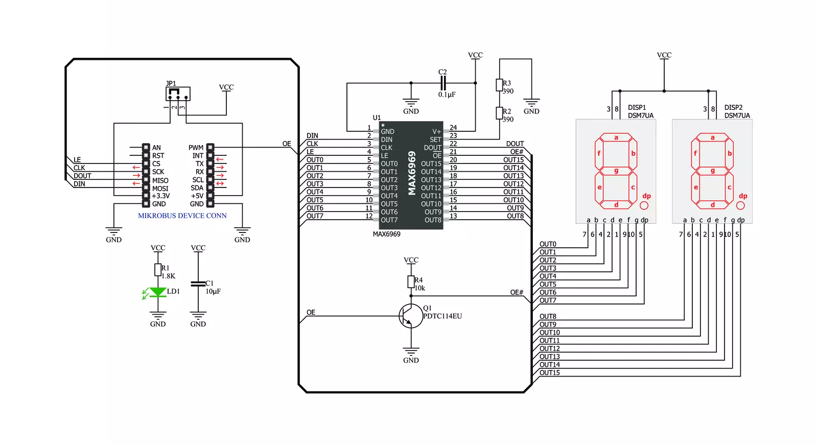
UT-M 7-SEG R Click is based on two medium-size red JSS-5611BUB-21s, ultra-thin single-digit numeric displays from Ningbo Junsheng Electronics. This high-intensity and reliable blue source color device is made with Indium-Gallium-Nitride light-emitting diode conducting material. It features low current operation, high light output, excellent character appearance, and is mechanically rugged. The display can work on 5V and 3.3V and has a common anode as its internal design. It consists of seven red LED segments that
form an 8 number and the eighth segment as a decimal point, or DP. The communication between the host MCU and the UT-M 7-SEG R Click is established via an industry-standard shift-register-plus-latch-type serial interface and the MAX6969, 16-port constant-current LED driver from Analog Devices. This driver has a 4-wire serial interface using four inputs and a data output. The output-enable input (OE) gates to all 16 outputs ON and OFF and is fast enough to be used as a PWM input for LED intensity control. The
constant-current outputs are programmed together to around 15mA using a single external resistor. This Click board™ can operate with either 3.3V or 5V logic voltage levels selected via the PWR SEL jumper. This way, both 3.3V and 5V capable MCUs can use the communication lines properly. Also, this Click board™ comes equipped with a library containing easy-to-use functions and an example code that can be used as a reference for further development.

Features overview
Development board
Flip&Click PIC32MZ is a compact development board designed as a complete solution that brings the flexibility of add-on Click boards™ to your favorite microcontroller, making it a perfect starter kit for implementing your ideas. It comes with an onboard 32-bit PIC32MZ microcontroller, the PIC32MZ2048EFH100 from Microchip, four mikroBUS™ sockets for Click board™ connectivity, two USB connectors, LED indicators, buttons, debugger/programmer connectors, and two headers compatible with Arduino-UNO pinout. Thanks to innovative manufacturing technology,
it allows you to build gadgets with unique functionalities and features quickly. Each part of the Flip&Click PIC32MZ development kit contains the components necessary for the most efficient operation of the same board. In addition, there is the possibility of choosing the Flip&Click PIC32MZ programming method, using the chipKIT bootloader (Arduino-style development environment) or our USB HID bootloader using mikroC, mikroBasic, and mikroPascal for PIC32. This kit includes a clean and regulated power supply block through the USB Type-C (USB-C) connector. All communication
methods that mikroBUS™ itself supports are on this board, including the well-established mikroBUS™ socket, user-configurable buttons, and LED indicators. Flip&Click PIC32MZ development kit allows you to create a new application in minutes. Natively supported by Mikroe software tools, it covers many aspects of prototyping thanks to a considerable number of different Click boards™ (over a thousand boards), the number of which is growing every day.

Microcontroller Overview
MCU Card / MCU

Architecture
PIC32
MCU Memory (KB)
2048
Silicon Vendor
Microchip
Pin count
100
RAM (Bytes)
524288
Used MCU Pins
mikroBUS™ mapper
Take a closer look
Click board™ Schematic
Step by step
Project assembly

Start by selecting your development board and Click board™. Begin with the Flip&Click PIC32MZ as your development board.


Software Support
Library Description
This library contains API for UT-M 7-SEG R Click driver.
Key functions:
utm7segr_generic_write- This function writes a desired number of data bytes starting from the selected register by using SPI serial interfaceutm7segr_display_state- This function turns display on and offutm7segr_display_number- This function is used to show the number on the display.
Open Source
Code example
The complete application code and a ready-to-use project are available through the NECTO Studio Package Manager for direct installation in the NECTO Studio. The application code can also be found on the MIKROE GitHub account.
/*!
 * @file main.c
 * @brief UT-M7-SEGR Click example
 *
 * # Description
 * The demo application shows basic usage of the UT-M 7-SEG display.
 *
 * The demo application is composed of two sections :
 *
 * ## Application Init
 * Configuring Clicks and log objects.
 * Settings the Click in the default configuration.
 *
 * ## Application Task
 * Draws numbers from 0 to 99 on the screen.
 *
 * @author Stefan Ilic
 *
 */

#include "board.h"
#include "log.h"
#include "utm7segr.h"

static utm7segr_t utm7segr;
static log_t logger;

void application_init ( void ) {
    log_cfg_t log_cfg;            /**< Logger config object. */
    utm7segr_cfg_t utm7segr_cfg;  /**< Click config object.  */

    /**
     * Logger initialization.
     * Default baud rate: 115200
     * Default log level: LOG_LEVEL_DEBUG
     * @note If USB_UART_RX and USB_UART_TX
     * are defined as HAL_PIN_NC, you will
     * need to define them manually for log to work.
     * See @b LOG_MAP_USB_UART macro definition for detailed explanation.
     */
    LOG_MAP_USB_UART( log_cfg );
    log_init( &logger, &log_cfg );
    log_info( &logger, "---- Application Init ----" );

    // Click initialization.

    utm7segr_cfg_setup( &utm7segr_cfg );
    UTM7SEGR_MAP_MIKROBUS( utm7segr_cfg, MIKROBUS_1 );
    err_t init_flag  = utm7segr_init( &utm7segr, &utm7segr_cfg );
    if ( init_flag == SPI_MASTER_ERROR ) {
        log_error( &logger, " Application Init Error. " );
        log_info( &logger, " Please, run program again... " );

        for ( ; ; );
    }

    utm7segr_default_cfg ( &utm7segr );
    log_info( &logger, " Application Task " );
}

void application_task ( void ) {
    log_info( &logger, "---- Number counter ----" );

    for ( uint8_t cnt = 0; cnt < 100; cnt++ ) {
        utm7segr_display_number( &utm7segr, cnt, UTM7SEGR_DOT_LEFT );
        Delay_ms ( 500 );
    }
}

int main ( void )
{
    /* Do not remove this line or clock might not be set correctly. */
    #ifdef PREINIT_SUPPORTED
    preinit();
    #endif

    application_init( );

    for ( ; ; )
    {
        application_task( );
    }

    return 0;
}

// ------------------------------------------------------------------------ END
Additional Support
Resources
Category:LED Segment


