Deliver clear and efficient data representation with TLC59283 and PIC18F57Q43
Visualize data with ease!

Published Feb 13, 2024
Click board™
BarGraph 4 Click
Dev. board
Curiosity Nano with PIC18F57Q43
Compiler
NECTO Studio
MCU
PIC18F57Q43
Captivate your audience with dynamic, attention-grabbing green bar graph that provide real-time insights and keep users engaged
A
A
Hardware Overview
How does it work?
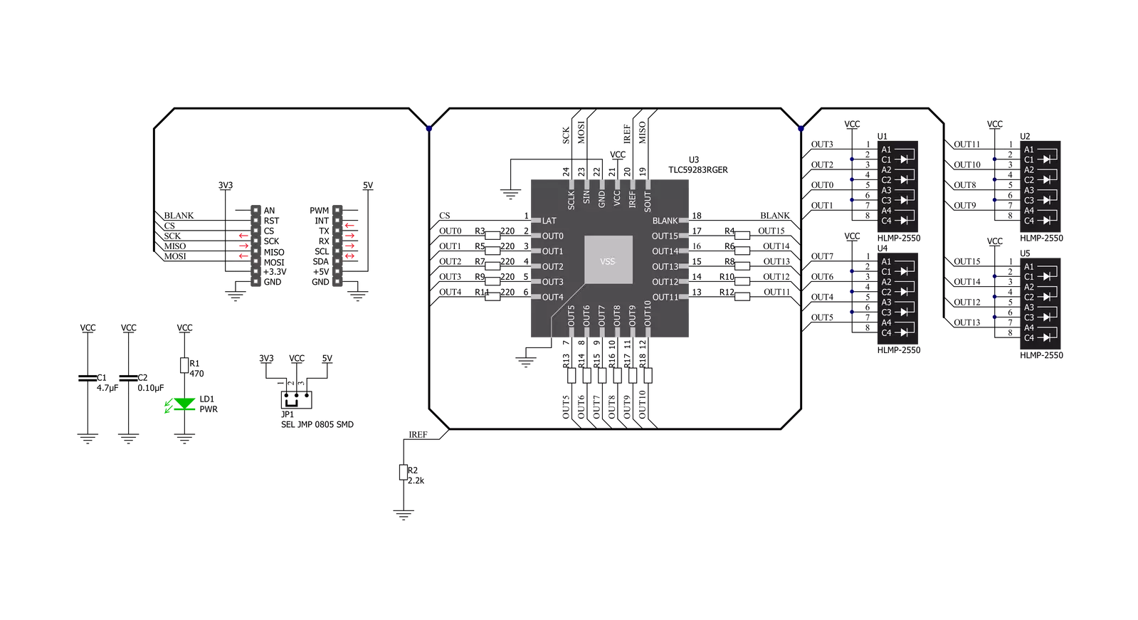
BarGraph 4 Click is based on the TLC59283, a 16-channel, constant-current sink light-emitting diode (LED) driver from Texas Instruments. Each channel can be individually controlled with a simple serial communications protocol compatible with 3.3V or 5V logic levels, depending on the operating VCC. It also comes with a constant-current value of all 16 channels, determined by an external resistor R2 with a value of 2.2kΩ, limiting the current to 24mA. You can find the exact value of the current per channel, as well as the corresponding resistance value for a given current, in the attached datasheet. In the upper part on the front side of the board, marked with the characters A, B, C, and D, four green four-segment LED bar graph displays, the HLMP-2550 are placed. The Green HLMP-2500 series LEDs use
a liquid phase GaPepitaxial layer on a GaP substrate. These light bars are designed for various applications requiring a large bright light source, making this Click board™ suitable for creating different VU meters, status indicators, counters, and similar devices. The TLC59283 communicates with MCU using the standard SPI serial interface with a maximum frequency of 35MHz. It has a 16-bit shift register and an output ON/OFF data latch. Both shift register and data latch are 16 bits long and used to turn the constant-current outputs on and off. It also comes with one GPIO pin, routed on the RST pin of the mikroBUS™ socket, used to turn off all outputs during Power-On and output data latching to prevent unwanted image displays during these times. When the device is powered on, the data in the 16-bit shift register and output
on or off data latch are not set to default values. Therefore, the output ON/PFF data must be written to the data latch before turning the constant-current output ON. The RST pin should be high when powered on because the constant current may be turned ON due to random data in the output on or off data latch. This Click board™ can operate with either 3.3V or 5V logic voltage levels selected via the VCC SEL jumper. This way, both 3.3V and 5V capable MCUs can use the communication lines properly. Also, this Click board™ comes equipped with a library containing easy-to-use functions and an example code that can be used as a reference for further development.


Features overview
Development board
PIC18F57Q43 Curiosity Nano evaluation kit is a cutting-edge hardware platform designed to evaluate microcontrollers within the PIC18-Q43 family. Central to its design is the inclusion of the powerful PIC18F57Q43 microcontroller (MCU), offering advanced functionalities and robust performance. Key features of this evaluation kit include a yellow user LED and a responsive
mechanical user switch, providing seamless interaction and testing. The provision for a 32.768kHz crystal footprint ensures precision timing capabilities. With an onboard debugger boasting a green power and status LED, programming and debugging become intuitive and efficient. Further enhancing its utility is the Virtual serial port (CDC) and a debug GPIO channel (DGI
GPIO), offering extensive connectivity options. Powered via USB, this kit boasts an adjustable target voltage feature facilitated by the MIC5353 LDO regulator, ensuring stable operation with an output voltage ranging from 1.8V to 5.1V, with a maximum output current of 500mA, subject to ambient temperature and voltage constraints.

Microcontroller Overview
MCU Card / MCU

Architecture
PIC
MCU Memory (KB)
128
Silicon Vendor
Microchip
Pin count
48
RAM (Bytes)
8196
You complete me!
Accessories
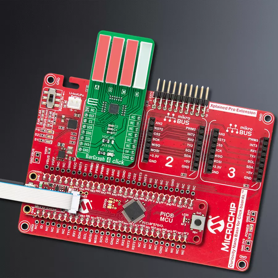
Curiosity Nano Base for Click boards is a versatile hardware extension platform created to streamline the integration between Curiosity Nano kits and extension boards, tailored explicitly for the mikroBUS™-standardized Click boards and Xplained Pro extension boards. This innovative base board (shield) offers seamless connectivity and expansion possibilities, simplifying experimentation and development. Key features include USB power compatibility from the Curiosity Nano kit, alongside an alternative external power input option for enhanced flexibility. The onboard Li-Ion/LiPo charger and management circuit ensure smooth operation for battery-powered applications, simplifying usage and management. Moreover, the base incorporates a fixed 3.3V PSU dedicated to target and mikroBUS™ power rails, alongside a fixed 5.0V boost converter catering to 5V power rails of mikroBUS™ sockets, providing stable power delivery for various connected devices.

Used MCU Pins
mikroBUS™ mapper
Take a closer look
Click board™ Schematic
Step by step
Project assembly

Start by selecting your development board and Click board™. Begin with the Curiosity Nano with PIC18F57Q43 as your development board.


Software Support
Library Description
This library contains API for BarGraph 4 Click driver.
Key functions:
bargraph4_enable_output- This function enables all outputsbargraph4_set_output- This function sets all outputs to desired value by using SPI serial interfacebargraph4_set_channel_level- This function sets the level of a desired bar graph channel.
Open Source
Code example
The complete application code and a ready-to-use project are available through the NECTO Studio Package Manager for direct installation in the NECTO Studio. The application code can also be found on the MIKROE GitHub account.
/*!
 * @file main.c
 * @brief BarGraph4 Click example
 *
 * # Description
 * This example demonstrates the use of BarGraph 4 Click board.
 *
 * The demo application is composed of two sections :
 *
 * ## Application Init
 * Initializes the driver and enables output.
 *
 * ## Application Task
 * Changes the level of all bar graph channels every second.
 * The channels level will be logged on the USB UART.
 *
 * @author Stefan Filipovic
 *
 */

#include "board.h"
#include "log.h"
#include "bargraph4.h"

static bargraph4_t bargraph4;
static log_t logger;

void application_init ( void )
{
    log_cfg_t log_cfg;              /**< Logger config object. */
    bargraph4_cfg_t bargraph4_cfg;  /**< Click config object. */

    /**
     * Logger initialization.
     * Default baud rate: 115200
     * Default log level: LOG_LEVEL_DEBUG
     * @note If USB_UART_RX and USB_UART_TX
     * are defined as HAL_PIN_NC, you will
     * need to define them manually for log to work.
     * See @b LOG_MAP_USB_UART macro definition for detailed explanation.
     */
    LOG_MAP_USB_UART( log_cfg );
    log_init( &logger, &log_cfg );
    Delay_ms ( 100 );
    log_info( &logger, " Application Init " );

    // Click initialization.

    bargraph4_cfg_setup( &bargraph4_cfg );
    BARGRAPH4_MAP_MIKROBUS( bargraph4_cfg, MIKROBUS_1 );
    err_t init_flag  = bargraph4_init( &bargraph4, &bargraph4_cfg );
    if ( SPI_MASTER_ERROR == init_flag )
    {
        log_error( &logger, " Application Init Error. " );
        log_info( &logger, " Please, run program again... " );

        for ( ; ; );
    }

    bargraph4_enable_output( &bargraph4 );
    log_info( &logger, " Application Task " );
}

void application_task ( void )
{
    for ( bargraph4_level_t cnt = BARGRAPH4_LEVEL_0; cnt <= BARGRAPH4_LEVEL_4; cnt++ )
    {
        bargraph4_set_channel_level( &bargraph4, BARGRAPH4_CHANNEL_A, cnt );
        bargraph4_set_channel_level( &bargraph4, BARGRAPH4_CHANNEL_B, cnt );
        bargraph4_set_channel_level( &bargraph4, BARGRAPH4_CHANNEL_C, cnt );
        bargraph4_set_channel_level( &bargraph4, BARGRAPH4_CHANNEL_D, cnt );
        log_printf( &logger, " All channels set to level %u\r\n\n", ( uint16_t ) cnt );
        Delay_ms ( 1000 );
    }
}

int main ( void )
{
    /* Do not remove this line or clock might not be set correctly. */
    #ifdef PREINIT_SUPPORTED
    preinit();
    #endif

    application_init( );

    for ( ; ; )
    {
        application_task( );
    }

    return 0;
}

// ------------------------------------------------------------------------ END
Additional Support
Resources
Category:LED Segment


