Ensure clear and visible information presentation with JS1-5213AE and STM32F031K6
Illuminate your data with decimal precision

Published Oct 01, 2024
Click board™
7seg Click
Dev. board
Nucleo 32 with STM32F031K6 MCU
Compiler
NECTO Studio
MCU
STM32F031K6
Straightforward solution for incorporating numeric or hexadecimal displays into electronic applications
A
A
Hardware Overview
How does it work?
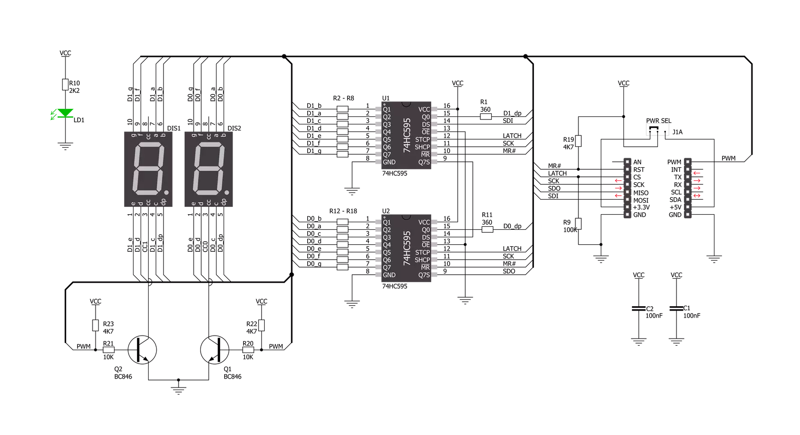
7seg Click is based on two seven-segment red LED displays, the JS1-5213AE from Ningbo Junsheng Electronics, driven by the SN74HC595D, an 8-bit serial-in, parallel-out shift register module from Texas Instruments. The JS1-5213AE display consists of seven LEDs arranged in a rectangular fashion, where each of the seven LEDs is called a segment because when illuminated, the segment forms part of a numerical digit (both decimal and hex) to be displayed. With dimensions of 17.5x12.4x8.4mm and a decimal point, these displays are also characterized by a wide viewing
range and ultra-segment intensity. This board is suitable for numeric or hexadecimal displays, such as clocks, timers, counters, or similar applications. As mentioned, this Click board™ communicates with MCU through a standard SPI interface across SN74HC595D with a maximum frequency of 5MHz. In addition to the SPI communication, the 7seg Click uses two additional pins for the direct shift register override function and display activation routed to the RST and PWM pins of the mikroBUS™ socket. Setting the PWM pin to logic high state turns the displays ON. After that, users
can see the functionality of the 7seg click by showing numbers or characters on the left and right displays. This Click board™ can operate with either 3.3V or 5V logic voltage levels selected via the PWR SEL jumper. This way, both 3.3V and 5V capable MCUs can use the communication lines properly. Also, this Click board™ comes equipped with a library containing easy-to-use functions and an example code that can be used as a reference for further development.

Features overview
Development board
Nucleo 32 with STM32F031K6 MCU board provides an affordable and flexible platform for experimenting with STM32 microcontrollers in 32-pin packages. Featuring Arduino™ Nano connectivity, it allows easy expansion with specialized shields, while being mbed-enabled for seamless integration with online resources. The
board includes an on-board ST-LINK/V2-1 debugger/programmer, supporting USB reenumeration with three interfaces: Virtual Com port, mass storage, and debug port. It offers a flexible power supply through either USB VBUS or an external source. Additionally, it includes three LEDs (LD1 for USB communication, LD2 for power,
and LD3 as a user LED) and a reset push button. The STM32 Nucleo-32 board is supported by various Integrated Development Environments (IDEs) such as IAR™, Keil®, and GCC-based IDEs like AC6 SW4STM32, making it a versatile tool for developers.

Microcontroller Overview
MCU Card / MCU

Architecture
ARM Cortex-M0
MCU Memory (KB)
32
Silicon Vendor
STMicroelectronics
Pin count
32
RAM (Bytes)
4096
You complete me!
Accessories
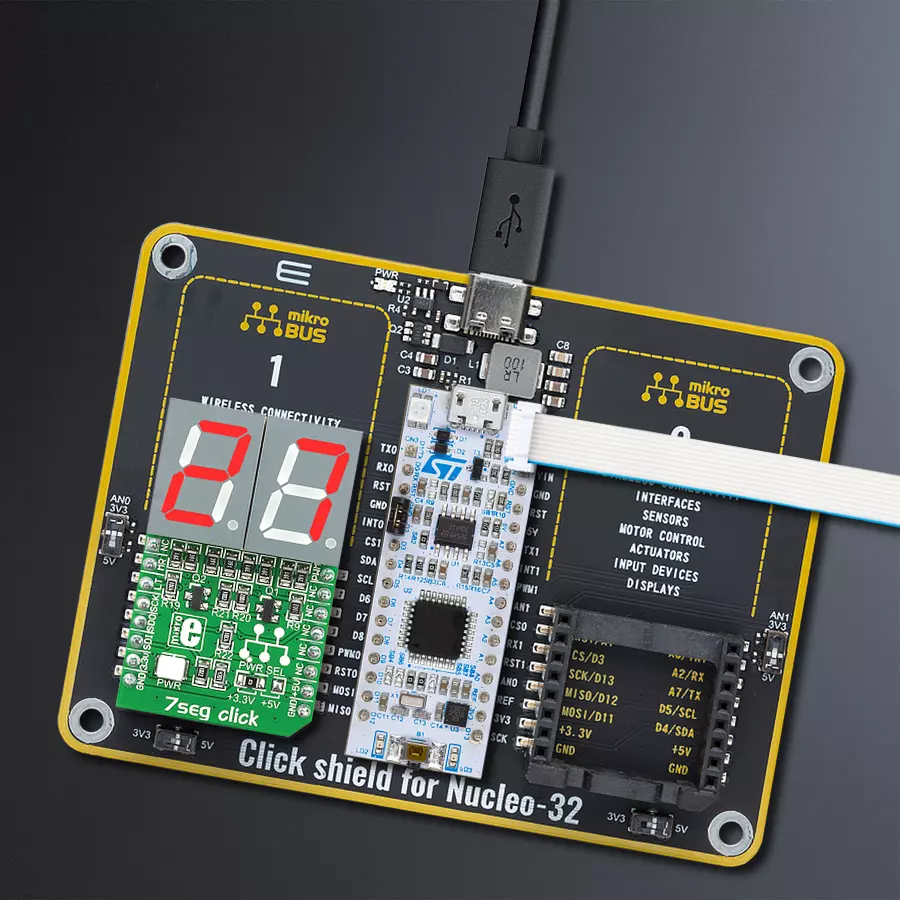
Click Shield for Nucleo-32 is the perfect way to expand your development board's functionalities with STM32 Nucleo-32 pinout. The Click Shield for Nucleo-32 provides two mikroBUS™ sockets to add any functionality from our ever-growing range of Click boards™. We are fully stocked with everything, from sensors and WiFi transceivers to motor control and audio amplifiers. The Click Shield for Nucleo-32 is compatible with the STM32 Nucleo-32 board, providing an affordable and flexible way for users to try out new ideas and quickly create prototypes with any STM32 microcontrollers, choosing from the various combinations of performance, power consumption, and features. The STM32 Nucleo-32 boards do not require any separate probe as they integrate the ST-LINK/V2-1 debugger/programmer and come with the STM32 comprehensive software HAL library and various packaged software examples. This development platform provides users with an effortless and common way to combine the STM32 Nucleo-32 footprint compatible board with their favorite Click boards™ in their upcoming projects.

Used MCU Pins
mikroBUS™ mapper
Take a closer look
Click board™ Schematic
Step by step
Project assembly

Start by selecting your development board and Click board™. Begin with the Nucleo 32 with STM32F031K6 MCU as your development board.


Software Support
Library Description
This library contains API for 7seg Click driver.
Key functions:
c7seg_display_mode- This function sets display state for 7seg Clickc7seg_write_data_number- This function writes left and right number on 7seg displayc7seg_write_data_character- This function writes left and right character on 7seg display
Open Source
Code example
The complete application code and a ready-to-use project are available through the NECTO Studio Package Manager for direct installation in the NECTO Studio. The application code can also be found on the MIKROE GitHub account.
/*!
 * \file
 * \brief 7seg Click example
 *
 * # Description
 * Example code consist of two sections: AppInit and AppTask,
 * and shows number or character on 7seg display.
 *
 * The demo application is composed of two sections :
 *
 * ## Application Init
 * Application Init performs Logger and Click Initialization.
 *
 * ## Application Task
 * Application Task shows functionality of the 7seg Click,
 * shows number or character on left and right display.
 *
 * \author Mihajlo Djordjevic
 *
 */
// ------------------------------------------------------------------- INCLUDES

#include "board.h"
#include "log.h"
#include "c7seg.h"

// ------------------------------------------------------------------ VARIABLES

static c7seg_t c7seg;
static log_t logger;

// ------------------------------------------------------ APPLICATION FUNCTIONS

void application_init ( void )
{
    log_cfg_t log_cfg;
    c7seg_cfg_t cfg;

    /**
     * Logger initialization.
     * Default baud rate: 115200
     * Default log level: LOG_LEVEL_DEBUG
     * @note If USB_UART_RX and USB_UART_TX
     * are defined as HAL_PIN_NC, you will
     * need to define them manually for log to work.
     * See @b LOG_MAP_USB_UART macro definition for detailed explanation.
     */
    LOG_MAP_USB_UART( log_cfg );
    log_init( &logger, &log_cfg );
    log_info( &logger, "---- Application Init ----" );

    //  Click initialization.

    c7seg_cfg_setup( &cfg );
    C7SEG_MAP_MIKROBUS( cfg, MIKROBUS_1 );
    c7seg_init( &c7seg, &cfg );

    c7seg_default_cfg ( &c7seg );
    Delay_ms ( 1000 );
}

void application_task ( void )
{
    uint8_t counter;

    c7seg_display_mode( &c7seg, C7SEG_DISPLAY_ON );
    Delay_ms ( 1000 );

    for ( counter = 0; counter < 9; counter ++ )
    {
        c7seg_write_data_number( &c7seg, counter, counter + 1 );
        Delay_ms ( 1000 );
    }
    Delay_ms ( 1000 );

    for ( counter = 65; counter < 90; counter ++ )
    {
        c7seg_write_data_character( &c7seg, counter, counter + 1 );
        Delay_ms ( 1000 );
    }
    Delay_ms ( 1000 );

    c7seg_display_mode( &c7seg, C7SEG_DISPLAY_OFF );
    Delay_ms ( 1000 );
}

int main ( void )
{
    /* Do not remove this line or clock might not be set correctly. */
    #ifdef PREINIT_SUPPORTED
    preinit();
    #endif

    application_init( );

    for ( ; ; )
    {
        application_task( );
    }

    return 0;
}

// ------------------------------------------------------------------------ END
Additional Support
Resources
Category:LED Segment


