Maintain complete control over your temperature-sensitive assets with EMC1833 and PIC18F2685
Stay in control, wherever you are!
Published Nov 01, 2023
Click board™
Remote Temp Click
Dev. board
EasyPIC v8
Compiler
NECTO Studio
MCU
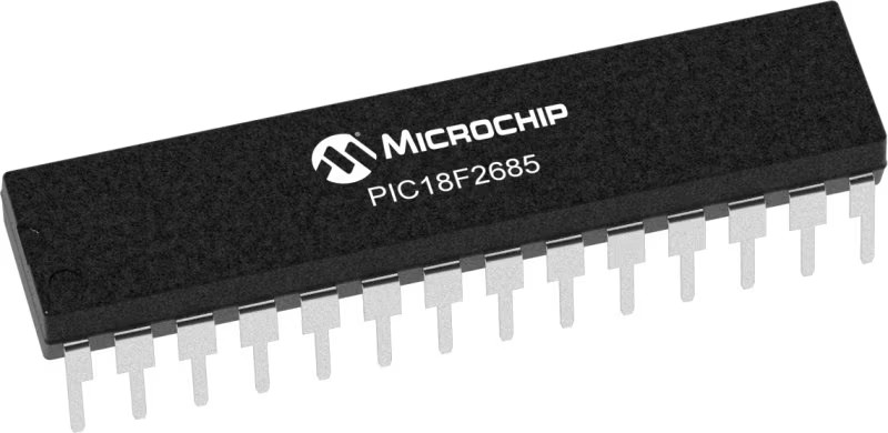
PIC18F2685
Relax and let our remote temperature sensing technology take the guesswork out of temperature management, ensuring your assets are always protected.
A
A
Hardware Overview
How does it work?
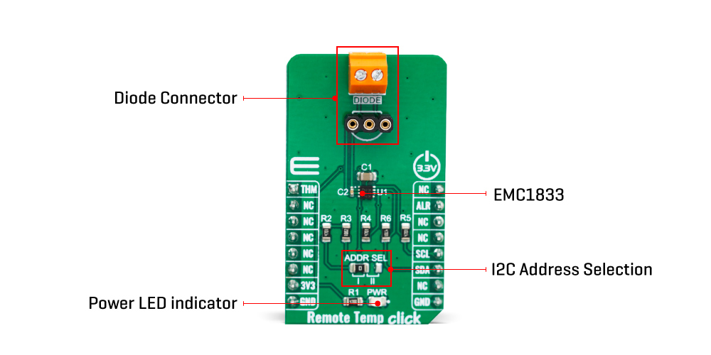
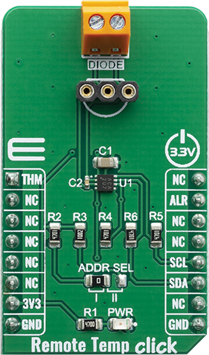
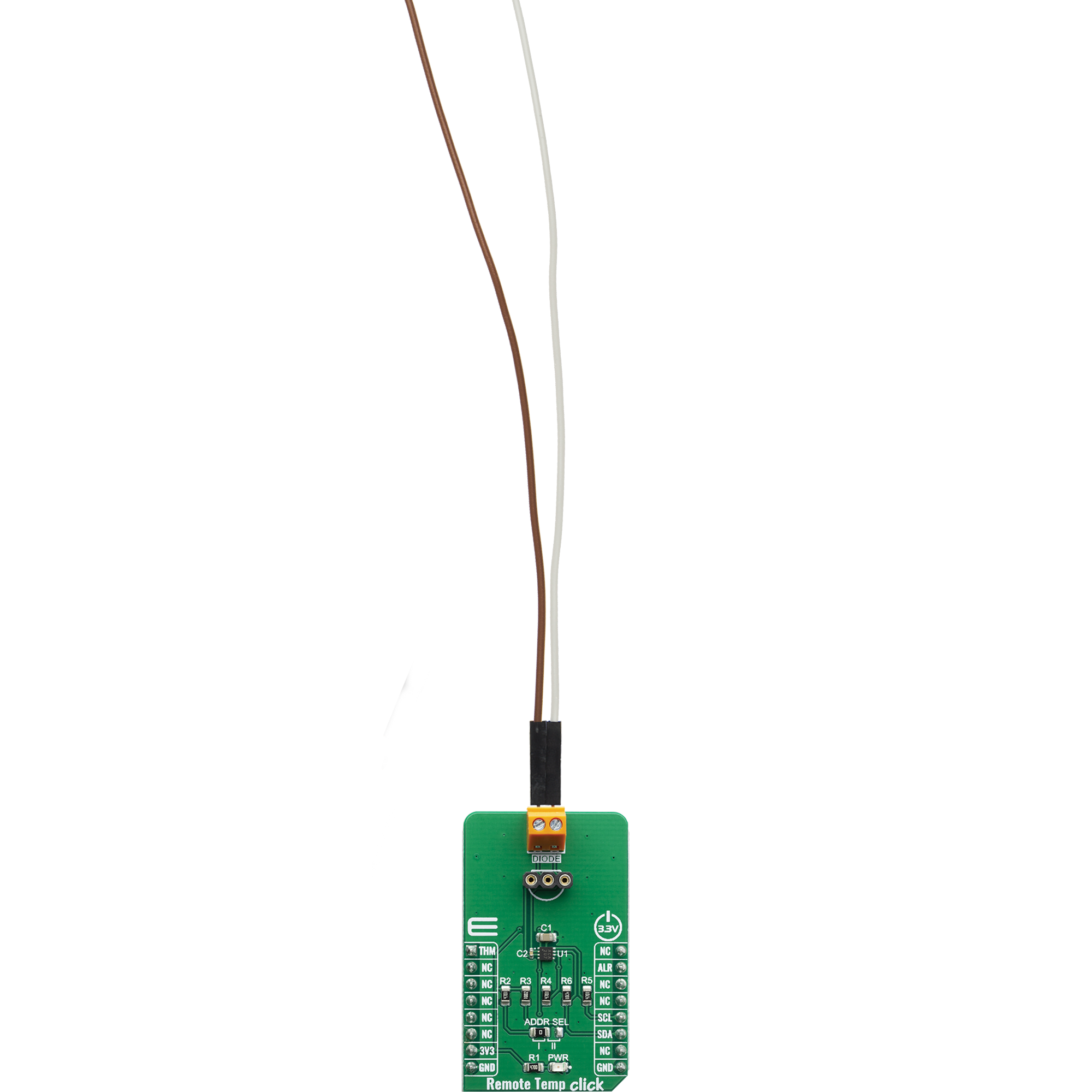
Remote Temp Click is based on the EMC1833, a ±1°C, SMBus/I2C compatible local/remote temperature sensor with an overtemperature alarm, produced by Microchip. This sensor is capable of measuring its own temperature, as well as the temperature of the remote BJT junction, which can be either a discrete PNP or NPN transistor, or a substrate of some integrated component (typically CPU, FPGA, ASIC or GPU). Substrate PNP transistors collector connected to the DP pin, a base connected to DN pin of EMC1833 and emitter is grounded. Discrete NPN transistor (2N3904) with its collector and base connected to DP pin, while the emitter is connected to the DN pin of the EMC1833. Anti-parallel connected discrete NPN transistors, collector and base of the first transistor connect to emitter of second transistor and DN2 pin of EMC1833, emitter of the first transistor connected to collector and base of second transistor and DP2 of pin EMC1833. There are some specific requirements for a discrete component when using it as a remote temperature sensor: for example, it has to be a small signal BJT. For more information, please refer to datasheet of the EMC1833, which also states some forward voltage ranges for the highest and the lowest expected temperatures and other parameters which should be considered when selecting the transistor. The discrete component can be connected to the screw
terminal at the edge of the Click board™. The EMC1833 features a 11-bit ADC which results in having the 0.125°C resolution. The temperature measurement results are stored in the internal and external temperature registers. Both external and internal temperature measurements are stored in 11-bit format with the eight Most Significant bits (MSb) stored in a high-byte register and the three Least Significant bits (LSb) stored in the three MSB positions of the low-byte register. All other bits of the low-byte register are set to zero. The EMC1833 IC automatically sends biasing current through the BJT junctions, while the IC samples the forward voltage for the given current and calculates the temperature. The ADC integrates the result over a period of 21ms, reducing the noise that way. Therefore, the temperature acquisition is not particularly fast. In return, the temperature measurement results are more accurate and reliable. The accuracy of the remote measurement depends on the ideality factor of the remote BJT junction. Not all external diodes, processor or discrete, will have this exact value. This variation of the ideality factor introduces errors in the temperature measurement which must be corrected for. Therefore, the EMC1833 features Programmable External Diode Ideality Factor, which can be easily set by changing the value in the appropriate register. The EMC1833 IC also features the ALERT
reporting capability. If a programmed threshold is exceeded, the ALERT pin will be asserted to a LOW logic level. When the ALERT pin is asserted, it will remain latched until its STATUS register is read after the overtemperature condition no longer exists. Another way to clear the ALERT interrupt is to respond to the alert response address. This is a global I2C/SMBus protocol, where the host MCU broadcasts a Receive Byte transmission after the interrupt is received. One (or more) slave devices which generated this interrupt will respond, sending their I2C slave address, following the bus arbitration rules. This protocol is explained in more details within the EMC1833 datasheet. The ALERT pin is routed to the INT pin of the mikroBUS™ and it is pulled up by a resistor. The slave address decode is performed by pulling known currents from the VDD pin through the external resistor, causing the pin voltage to drop based on the respective current/resistor relationship. This pin voltage is compared against a threshold that determines the value of the pull-up resistor. This Click Board™ is designed to be operated only with 3.3V logic level. A proper logic voltage level conversion should be performed before the Click board™ is used with MCUs with logic levels of 5V. It is ready to be used as soon as it is inserted into a mikroBUS™ socket of the development system.
Features overview
Development board
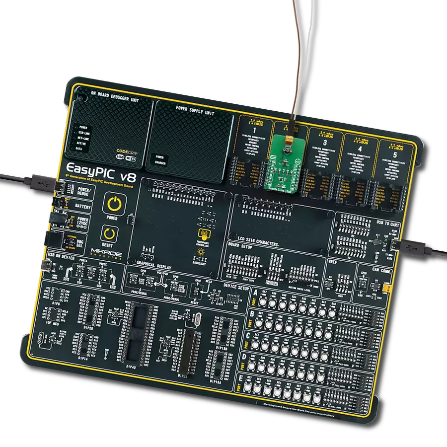
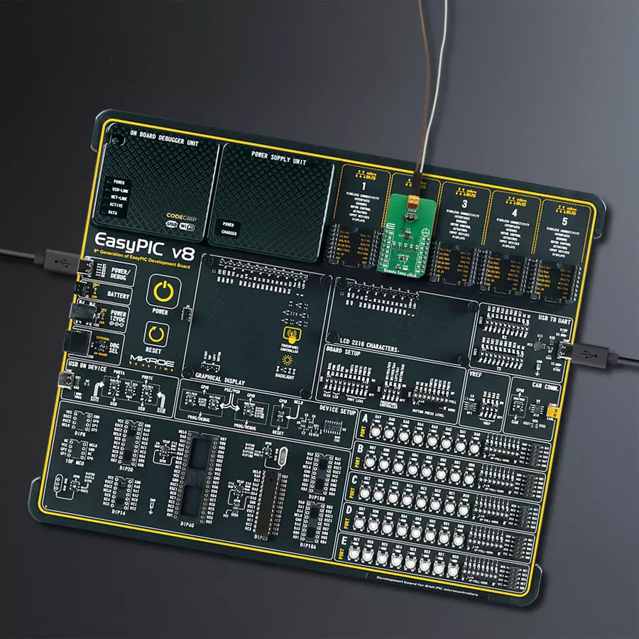
EasyPIC v8 is a development board specially designed for the needs of rapid development of embedded applications. It supports many high pin count 8-bit PIC microcontrollers from Microchip, regardless of their number of pins, and a broad set of unique functions, such as the first-ever embedded debugger/programmer. The development board is well organized and designed so that the end-user has all the necessary elements, such as switches, buttons, indicators, connectors, and others, in one place. Thanks to innovative manufacturing technology, EasyPIC v8 provides a fluid and immersive working experience, allowing access anywhere and under any
circumstances at any time. Each part of the EasyPIC v8 development board contains the components necessary for the most efficient operation of the same board. In addition to the advanced integrated CODEGRIP programmer/debugger module, which offers many valuable programming/debugging options and seamless integration with the Mikroe software environment, the board also includes a clean and regulated power supply module for the development board. It can use a wide range of external power sources, including a battery, an external 12V power supply, and a power source via the USB Type-C (USB-C) connector.
Communication options such as USB-UART, USB DEVICE, and CAN are also included, including the well-established mikroBUS™ standard, two display options (graphical and character-based LCD), and several different DIP sockets. These sockets cover a wide range of 8-bit PIC MCUs, from the smallest PIC MCU devices with only eight up to forty pins. EasyPIC v8 is an integral part of the Mikroe ecosystem for rapid development. Natively supported by Mikroe software tools, it covers many aspects of prototyping and development thanks to a considerable number of different Click boards™ (over a thousand boards), the number of which is growing every day.

Microcontroller Overview
MCU Card / MCU
Architecture
PIC
MCU Memory (KB)
96
Silicon Vendor
Microchip
Pin count
28
RAM (Bytes)
3328
Used MCU Pins
mikroBUS™ mapper
Take a closer look
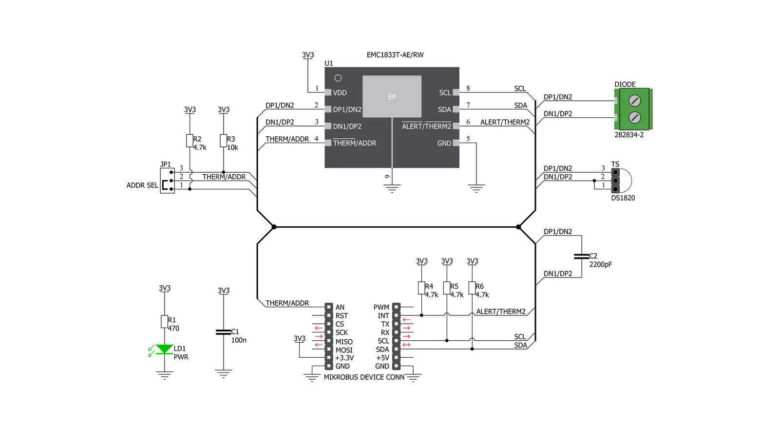
Click board™ Schematic
Step by step
Project assembly

Start by selecting your development board and Click board™. Begin with the EasyPIC v8 as your development board.


Software Support
Library Description
This library contains API for Remote Temp Click driver.
Key functions:
remotetemp_int_get- Getting state of INT pin.remotetemp_an_get- Getting state of AN pin.remotetemp_set_range- Setting temperature range.
Open Source
Code example
The complete application code and a ready-to-use project are available through the NECTO Studio Package Manager for direct installation in the NECTO Studio. The application code can also be found on the MIKROE GitHub account.
/*!
 * \file
 * \brief RemoteTemp Click example
 *
 * # Description
 * This application reads remote temperature data.
 *
 * The demo application is composed of two sections :
 *
 * ## Application Init
 * Initializes I2C driver, sets range, configures device and sets threshold values.
 *
 * ## Application Task
 * Executes all 'remotetemp_aux_getXxx()' functions.
 *
 *
 * \author MikroE Team
 *
 */
// ------------------------------------------------------------------- INCLUDES

#include "board.h"
#include "log.h"
#include "remotetemp.h"

// ------------------------------------------------------------------ VARIABLES

static remotetemp_t remotetemp;
static log_t logger;

// ------------------------------------------------------ APPLICATION FUNCTIONS

void remotetemp_aux_get_fault ( remotetemp_t *ctx )
{
    uint8_t aux_byte[ 1 ];

    remotetemp_read( ctx, REMOTETEMP_EXTERNAL_DIODE_FAULT_STATUS, &aux_byte[ 0 ], 1 );
    if ( aux_byte[ 0 ] != 0 )
    {
        if ( ( aux_byte[ 0 ] & 0x02 ) == 0x02 )
        {
            log_printf( &logger, "  - external diode 1 \r\n" );
        }
    }
}

void remotetemp_aux_get_high_limit_status ( remotetemp_t *ctx )
{
    float internal_temp;
    float external_1_temp;
    float external_2_temp;
    uint8_t aux_byte[ 1 ];

    remotetemp_read( ctx, REMOTETEMP_HIGH_LIMIT_STATUS, &aux_byte[ 0 ], 1 );
    if ( aux_byte[ 0 ] != 0 )
    {
        log_printf( &logger, "> high threshold limit exceeded by : \r\n" );

        if ( ( aux_byte[ 0 ] & 0x01 ) == 0x01 )
        {
            log_printf( &logger, "  - internal diode \r\n" );
            internal_temp = remotetemp_get_internal_diode( ctx );
            log_printf( &logger, "  - temperature : %f degC \r\n", internal_temp );
        }
        if ( ( aux_byte[ 0 ] & 0x02 ) == 0x02 )
        {
            log_printf( &logger, "  - external diode 1 \r\n" );
            external_1_temp = remotetemp_get_external_diode( ctx, 1 );
            log_printf( &logger, "  - temperature : %f degC \r\n", external_1_temp );
        }
        if ( ( aux_byte[ 0 ] & 0x04 ) == 0x04 )
        {
            log_printf( &logger, "  - external diode 2 \r\n" );
            external_2_temp = remotetemp_get_external_diode( ctx, 2 );
            log_printf( &logger, "  - temperature : %f degC \r\n", external_2_temp );
        }
    }
}

void remotetemp_aux_get_low_limit_status ( remotetemp_t *ctx )
{
    float internal_temp;
    float external_1_temp;
    float external_2_temp;
    uint8_t aux_byte[ 1 ];

    remotetemp_read( ctx, REMOTETEMP_LOW_LIMIT_STATUS, &aux_byte[ 0 ], 1 );
    if ( aux_byte[ 0 ] != 0 )
    {
        log_printf( &logger, "> > low threshold limit exceeded by : \r\n" );

        if ( ( aux_byte[ 0 ] & 0x01 ) == 0x01 )
        {
            log_printf( &logger, "  - internal diode \r\n" );
            internal_temp = remotetemp_get_internal_diode( ctx );
            log_printf( &logger, "  - temperature : %f degC \r\n", internal_temp );
        }
        if ( ( aux_byte[ 0 ] & 0x02 ) == 0x02 )
        {
            log_printf( &logger, "  - external diode 1 \r\n" );
            external_1_temp = remotetemp_get_external_diode( ctx, 1 );
            log_printf( &logger, "  - temperature : %f degC \r\n", external_1_temp );
        }
        if ( ( aux_byte[ 0 ] & 0x04 ) == 0x04 )
        {
            log_printf( &logger, "  - external diode 2 \r\n" );
            external_2_temp = remotetemp_get_external_diode( ctx, 2 );
            log_printf( &logger, "  - temperature : %f degC \r\n", external_2_temp );
        }
    }
}

void remotetemp_aux_get_therm_limit_status ( remotetemp_t *ctx )
{
    float internal_temp;
    float external_1_temp;
    float external_2_temp;
    uint8_t aux_byte[ 1 ];

    remotetemp_read( ctx, REMOTETEMP_THERM_LIMIT_STATUS, &aux_byte[ 0 ], 1 );
    if ( aux_byte[ 0 ] != 0 )
    {
        log_printf( &logger, "> therm threshold limit exceeded by : \r\n" );

        if ( ( aux_byte[ 0 ] & 0x01 ) == 0x01 )
        {
            log_printf( &logger, "  - internal diode \r\n" );
            internal_temp = remotetemp_get_internal_diode( ctx );
            log_printf( &logger, "  - temperature : %f degC \r\n", internal_temp );
        }
        if ( ( aux_byte[ 0 ] & 0x02 ) == 0x02 )
        {
            log_printf( &logger, "  - external diode 1 \r\n" );
            external_1_temp = remotetemp_get_external_diode( ctx, 1 );
            log_printf( &logger, "  - temperature : %f degC \r\n", external_1_temp );
        }
        if ( ( aux_byte[ 0 ] & 0x04 ) == 0x04 )
        {
            log_printf( &logger, "  - external diode 2 \r\n" );
            external_2_temp = remotetemp_get_external_diode( ctx, 2 );
            log_printf( &logger, "  - temperature : %f degC \r\n", external_2_temp );
        }
    }
}

void remotetemp_aux_get_hottest_status ( remotetemp_t *ctx )
{
    float hottest_temp;
    uint8_t aux_byte[ 1 ];

    remotetemp_read( ctx, REMOTETEMP_HOTTEST_STATUS, &aux_byte[ 0 ], 1 );
    if ( aux_byte[ 0 ] != 0 )
    {
        log_printf( &logger, "> hottest diode : \r\n" );

        if ( ( aux_byte[ 0 ] & 0x01 ) == 0x01 )
        {
            log_printf( &logger, " - internal diode \r\n" );
        }
        else if ( ( aux_byte[ 0 ] & 0x02 ) == 0x02 )
        {
            log_printf( &logger, "  - external diode 1 \r\n" );
        }
        else if ( ( aux_byte[ 0 ] & 0x04 ) == 0x04 )
        {
            log_printf( &logger, "  - external diode 2 \r\n" );
        }
        hottest_temp = remotetemp_get_hottest_diode( ctx );
        log_printf( &logger, "  - temperature : %.2f degC \r\n", hottest_temp );
    }
    log_printf( &logger, "\r\n" );
}

void application_init ( void )
{
    log_cfg_t log_cfg;
    remotetemp_cfg_t cfg;

    /**
     * Logger initialization.
     * Default baud rate: 115200
     * Default log level: LOG_LEVEL_DEBUG
     * @note If USB_UART_RX and USB_UART_TX
     * are defined as HAL_PIN_NC, you will
     * need to define them manually for log to work.
     * See @b LOG_MAP_USB_UART macro definition for detailed explanation.
     */
    LOG_MAP_USB_UART( log_cfg );
    log_init( &logger, &log_cfg );
    log_info( &logger, "---- Application Init ----" );

    //  Click initialization.

    remotetemp_cfg_setup( &cfg );
    REMOTETEMP_MAP_MIKROBUS( cfg, MIKROBUS_1 );
    remotetemp_init( &remotetemp, &cfg );

    Delay_ms ( 300 );
    remotetemp_default_cfg( &remotetemp );
    log_printf( &logger, "> app init done \r\n" );
}

void application_task ( void )
{
    remotetemp_aux_get_fault( &remotetemp );
    remotetemp_aux_get_high_limit_status( &remotetemp );
    remotetemp_aux_get_low_limit_status( &remotetemp );
    remotetemp_aux_get_therm_limit_status( &remotetemp );
    remotetemp_aux_get_hottest_status( &remotetemp );
    Delay_ms ( 1000 );
}

int main ( void )
{
    /* Do not remove this line or clock might not be set correctly. */
    #ifdef PREINIT_SUPPORTED
    preinit();
    #endif

    application_init( );

    for ( ; ; )
    {
        application_task( );
    }

    return 0;
}

// ------------------------------------------------------------------------ END
Additional Support
Resources
Category:Temperature & humidity


