Precisely gauge surface temperature without any contact with AMG8853 and ATmega328P
The infrared marvel: Object heat, revealed!
Published Feb 14, 2024
Click board™
Grid-EYE Click
Dev. board
Arduino UNO Rev3
Compiler
NECTO Studio
MCU
ATmega328P
Say goodbye to physical contact and embrace wireless precision with our state-of-the-art infrared array sensor, unlocking the secrets of temperature through non-contact measurements
A
A
Hardware Overview
How does it work?
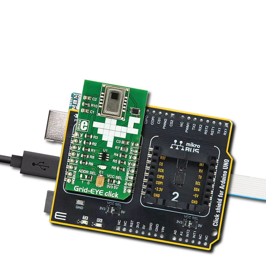
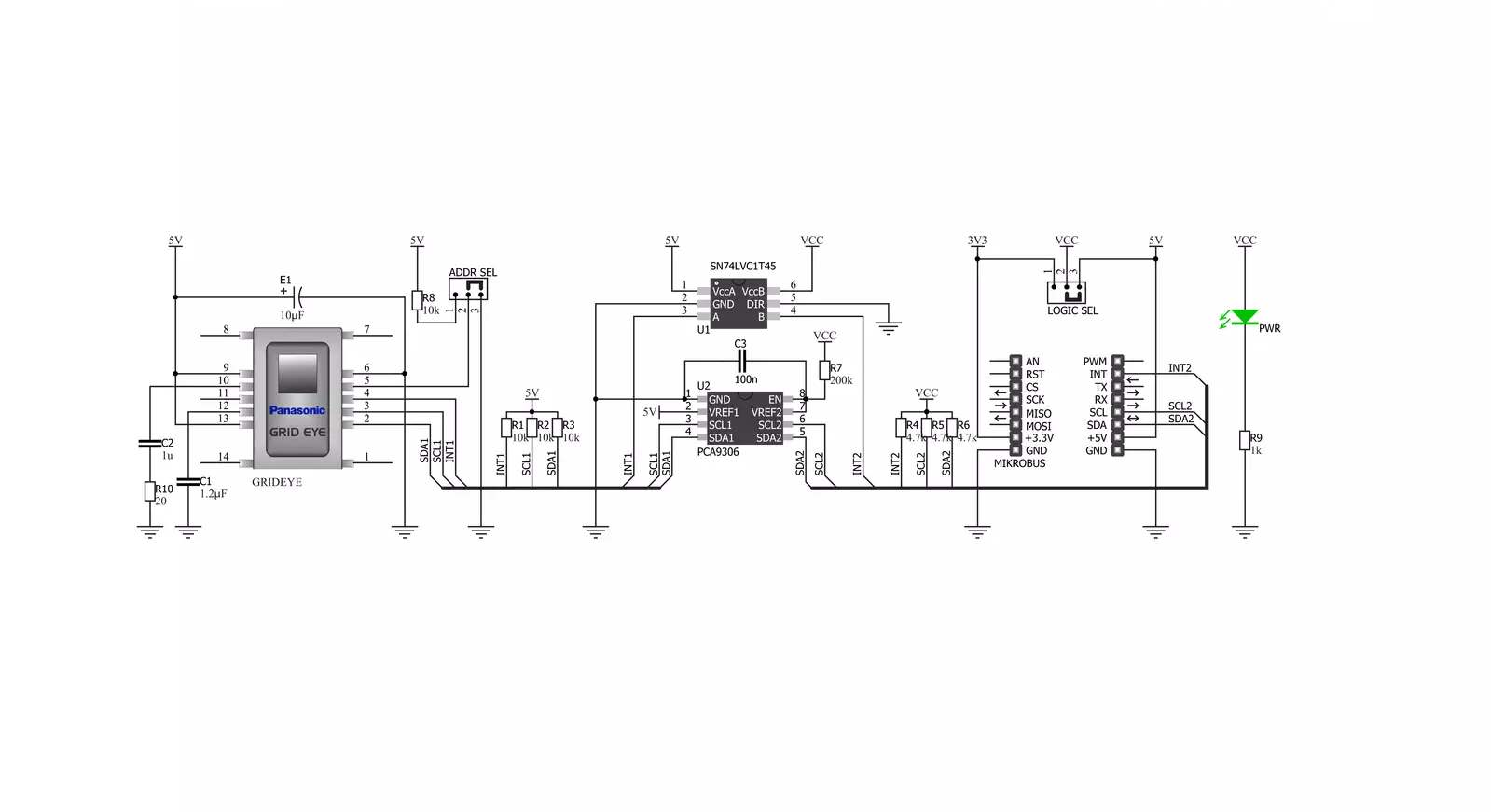
Grid-EYE Click is based on the AMG8853, an infrared array sensor from Panasonic Semi. It can detect the absolute surface temperature of an object without any contact, even a moving object such as a moving hand. The sensor senses the heat, so you don’t need light to form a picture. The temperature measuring range is from -20°C up to +100°C with a viewing angle of 60 degrees and a 5m detecting distance. It can be used in various applications. The AMG8853 has a built-in thermistor for suppressing ambient temperature noise. Infrared waves are outside the visible spectrum of the human eye, just like radio waves.
Even though people can’t see infrared waves, they can certainly feel them in the form of heat. Our bodies emit heat or infrared radiation, and the AMG8853 thermal array sensor can detect it. Grid-EYE Click uses a standard 2-Wire I2C interface to communicate with the host MCU, supporting fast mode. The I2C address can be selected over the ADDR SEL jumper with 0 selected by default. The AMG8853 works at 5V, and to work with a 3.3V logic level, this Click board™ features the PCA9306, a dual bidirectional I2C bus, and an SMBus voltage-level translator from Texas Instruments. The sensor features an interrupt
function over the INT pin. For logic level translation of the interrupt pin, this Click board™ uses the SN74LVC1T45, a single-bit dual-supply bus transceiver with configurable voltage translation and 3-state outputs from Texas Instruments. This Click board™ can operate with either 3.3V or 5V logic voltage levels selected via the VCC SEL jumper. This way, both 3.3V and 5V capable MCUs can use the communication lines properly. Also, this Click board™ comes equipped with a library containing easy-to-use functions and an example code that can be used as a reference for further development.


Features overview
Development board
Arduino UNO is a versatile microcontroller board built around the ATmega328P chip. It offers extensive connectivity options for various projects, featuring 14 digital input/output pins, six of which are PWM-capable, along with six analog inputs. Its core components include a 16MHz ceramic resonator, a USB connection, a power jack, an
ICSP header, and a reset button, providing everything necessary to power and program the board. The Uno is ready to go, whether connected to a computer via USB or powered by an AC-to-DC adapter or battery. As the first USB Arduino board, it serves as the benchmark for the Arduino platform, with "Uno" symbolizing its status as the
first in a series. This name choice, meaning "one" in Italian, commemorates the launch of Arduino Software (IDE) 1.0. Initially introduced alongside version 1.0 of the Arduino Software (IDE), the Uno has since become the foundational model for subsequent Arduino releases, embodying the platform's evolution.

Microcontroller Overview
MCU Card / MCU

Architecture
AVR
MCU Memory (KB)
32
Silicon Vendor
Microchip
Pin count
28
RAM (Bytes)
2048
You complete me!
Accessories
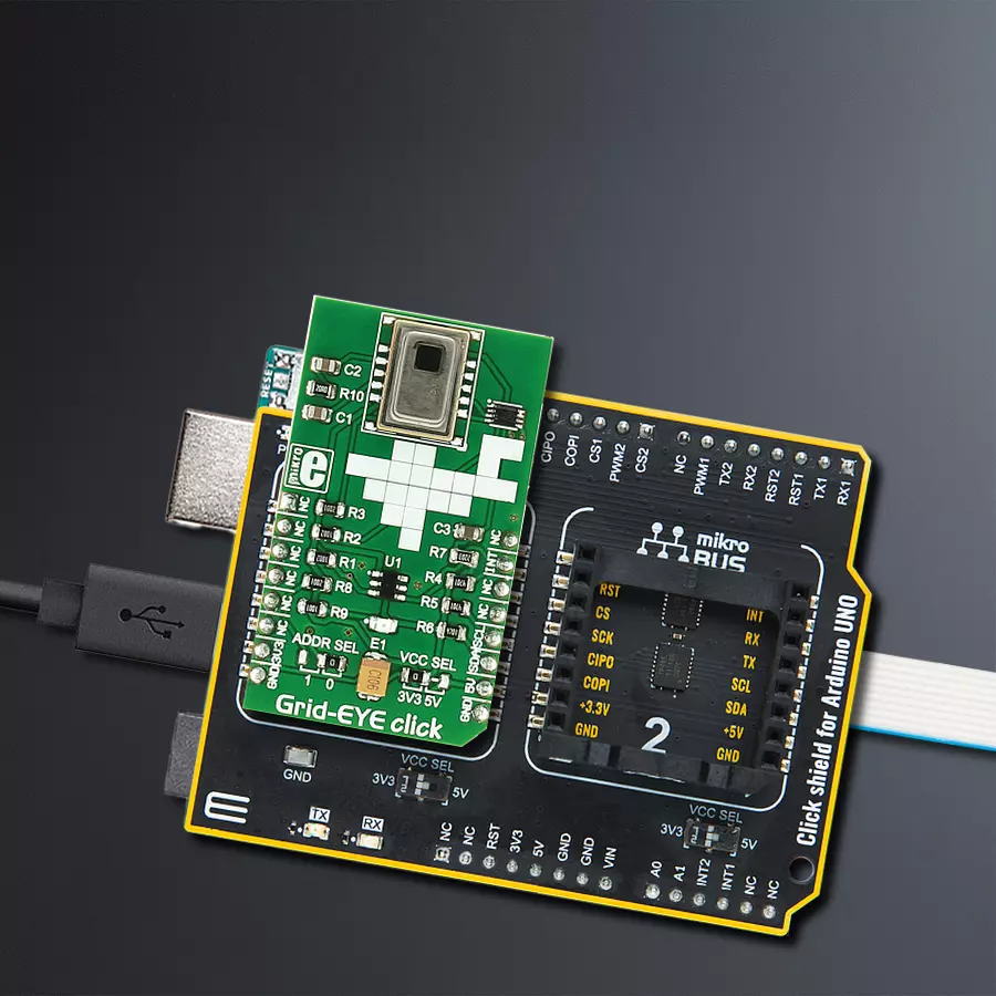
Click Shield for Arduino UNO has two proprietary mikroBUS™ sockets, allowing all the Click board™ devices to be interfaced with the Arduino UNO board without effort. The Arduino Uno, a microcontroller board based on the ATmega328P, provides an affordable and flexible way for users to try out new concepts and build prototypes with the ATmega328P microcontroller from various combinations of performance, power consumption, and features. The Arduino Uno has 14 digital input/output pins (of which six can be used as PWM outputs), six analog inputs, a 16 MHz ceramic resonator (CSTCE16M0V53-R0), a USB connection, a power jack, an ICSP header, and reset button. Most of the ATmega328P microcontroller pins are brought to the IO pins on the left and right edge of the board, which are then connected to two existing mikroBUS™ sockets. This Click Shield also has several switches that perform functions such as selecting the logic levels of analog signals on mikroBUS™ sockets and selecting logic voltage levels of the mikroBUS™ sockets themselves. Besides, the user is offered the possibility of using any Click board™ with the help of existing bidirectional level-shifting voltage translators, regardless of whether the Click board™ operates at a 3.3V or 5V logic voltage level. Once you connect the Arduino UNO board with our Click Shield for Arduino UNO, you can access hundreds of Click boards™, working with 3.3V or 5V logic voltage levels.

Used MCU Pins
mikroBUS™ mapper
Take a closer look
Click board™ Schematic
Step by step
Project assembly

Start by selecting your development board and Click board™. Begin with the Arduino UNO Rev3 as your development board.


Software Support
Library Description
This library contains API for Grid-EYE Click driver.
Key functions:
grideye_generic_write- Generic write function.grideye_generic_read- Generic read function.grideye_write_data- Write data function.
Open Source
Code example
The complete application code and a ready-to-use project are available through the NECTO Studio Package Manager for direct installation in the NECTO Studio. The application code can also be found on the MIKROE GitHub account.
/*!
 * \file
 * \brief Grideye Click example
 *
 * # Description
 * 64 individual thermal sensors build an image on a display. The detecting distance is 5m.
 *
 * The demo application is composed of two sections :
 *
 * ## Application Init
 * Initalizes I2C driver, applies default settings, and makes an initial log.
 *
 * ## Application Task
 * This example demonstrates the use of Grid-EYE Click board by reading full grid and displaying values via USART terminal
 *
 *
 * \author MikroE Team
 *
 */
// ------------------------------------------------------------------- INCLUDES

#include "board.h"
#include "log.h"
#include "grideye.h"

#define GRIDEYE_TEMP_COEF  0.25

// ------------------------------------------------------------------ VARIABLES

static grideye_t grideye;
static log_t logger;

// ------------------------------------------------------ APPLICATION FUNCTIONS

void application_init ( void )
{
    log_cfg_t log_cfg;
    grideye_cfg_t cfg;

    /**
     * Logger initialization.
     * Default baud rate: 115200
     * Default log level: LOG_LEVEL_DEBUG
     * @note If USB_UART_RX and USB_UART_TX
     * are defined as HAL_PIN_NC, you will
     * need to define them manually for log to work.
     * See @b LOG_MAP_USB_UART macro definition for detailed explanation.
     */
    LOG_MAP_USB_UART( log_cfg );
    log_init( &logger, &log_cfg );
    log_info( &logger, "---- Application Init... ----" );

    //  Click initialization.

    grideye_cfg_setup( &cfg );
    GRIDEYE_MAP_MIKROBUS( cfg, MIKROBUS_1 );

    if ( grideye_init( &grideye, &cfg ) == GRIDEYE_INIT_ERROR )
    {
        log_info( &logger, "---- Application Init Error. ----" );
        log_info( &logger, "---- Please, run program again... ----" );

        for ( ; ; );
    }

    log_info( &logger, "---- Application Init Done. ----" );

    grideye_default_cfg ( &grideye );

    log_info( &logger, "---- Application Running... ----\n" );
}

void application_task ( void )
{
    uint8_t i;
    uint8_t j;
    int16_t grid_array[ 64 ];
    int16_t grid_array_tmp;

    grideye_read_grid( &grideye, grid_array );

    for( i = 1; i < 9; i++ )
    {
        for( j = 1; j < 9; j++ )
        {
            log_printf( &logger, "| " );
            grid_array_tmp = grid_array[ i * j - 1 ];

            log_printf( &logger, "%d ", (int16_t)( grid_array_tmp * GRIDEYE_TEMP_COEF ) );
        }
        log_printf( &logger, " \r\n" );
        log_printf( &logger, "-------------------------------------- \r\n" );
    }

    Delay_ms ( 1000 );
}

int main ( void )
{
    /* Do not remove this line or clock might not be set correctly. */
    #ifdef PREINIT_SUPPORTED
    preinit();
    #endif

    application_init( );

    for ( ; ; )
    {
        application_task( );
    }

    return 0;
}

// ------------------------------------------------------------------------ END
Additional Support
Resources
Category:Temperature & humidity


