Maintain the perfect indoor comfort level using AM2322 and ATmega2560
Climate insights for a healthier tomorrow!

Published Feb 14, 2024
Click board™
DHT22 2 Click
Dev. board
Arduino Mega 2560 Rev3
Compiler
NECTO Studio
MCU
ATmega2560
Our solution tracks environmental conditions, allowing you to be prepared for any weather event.
A
A
Hardware Overview
How does it work?
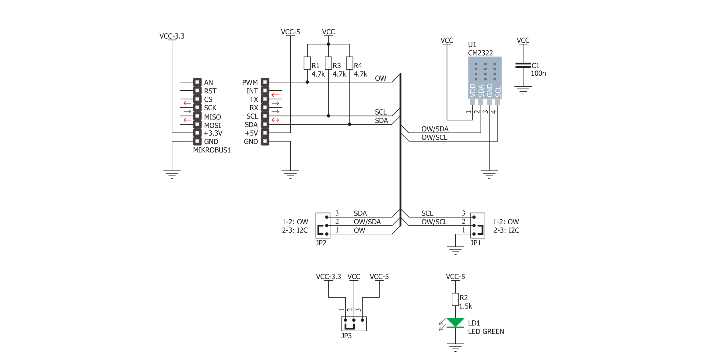
DHT22 2 Click is based on the CM2322, a temperature and relative humidity from Aosong. This sensor contains humidity and temperature measurement elements, compensated and calibrated in the accurate calibration chamber. The calibration coefficient is saved in the OTP memory of an integrated MCU. The integrated MCU also provides an I2C or 1-Wire interface, selectable by the onboard SMD jumper selectors. The onboard
SMD jumper can also select the operating voltage. Typical temperature accuracy is ±0.3°C, while relative humidity accuracy is 2% RH, with a resolution of 0.1 for both measured properties. I2C/1-Wire interface communicates with the host MCU, sending the measurement data every 2 seconds. Proprietary data collecting techniques are used to average the sampled values, after which the result is sent via the I2C/1-Wire bus. This
Click board™ can operate with either 3.3V or 5V logic voltage levels selected via the LOGIC SEL jumper. This way, both 3.3V and 5V capable MCUs can use the communication lines properly. Also, this Click board™ comes equipped with a library containing easy-to-use functions and an example code that can be used as a reference for further development.

Features overview
Development board
Arduino Mega 2560 is a robust microcontroller platform built around the ATmega 2560 chip. It has extensive capabilities and boasts 54 digital input/output pins, including 15 PWM outputs, 16 analog inputs, and 4 UARTs. With a 16MHz crystal
oscillator ensuring precise timing, it offers seamless connectivity via USB, a convenient power jack, an ICSP header, and a reset button. This all-inclusive board simplifies microcontroller projects; connect it to your computer via USB or power it up
using an AC-to-DC adapter or battery. Notably, the Mega 2560 maintains compatibility with a wide range of shields crafted for the Uno, Duemilanove, or Diecimila boards, ensuring versatility and ease of integration.

Microcontroller Overview
MCU Card / MCU

Architecture
AVR
MCU Memory (KB)
256
Silicon Vendor
Microchip
Pin count
100
RAM (Bytes)
8192
You complete me!
Accessories
Click Shield for Arduino Mega comes equipped with four mikroBUS™ sockets, with two in the form of a Shuttle connector, allowing all the Click board™ devices to be interfaced with the Arduino Mega board with no effort. Featuring an AVR 8-bit microcontroller with advanced RISC architecture, 54 digital I/O pins, and Arduino™ compatibility, the Arduino Mega board offers limitless possibilities for prototyping and creating diverse applications. This board is controlled and powered conveniently through a USB connection to program and debug the Arduino Mega board efficiently out of the box, with an additional USB cable connected to the USB B port on the board. Simplify your project development with the integrated ATmega16U2 programmer and unleash creativity using the extensive I/O options and expansion capabilities. There are eight switches, which you can use as inputs, and eight LEDs, which can be used as outputs of the MEGA2560. In addition, the shield features the MCP1501, a high-precision buffered voltage reference from Microchip. This reference is selected by default over the EXT REF jumper at the bottom of the board. You can choose an external one, as you would usually do with an Arduino Mega board. There is also a GND hook for testing purposes. Four additional LEDs are PWR, LED (standard pin D13), RX, and TX LEDs connected to UART1 (mikroBUS™ 1 socket). This Click Shield also has several switches that perform functions such as selecting the logic levels of analog signals on mikroBUS™ sockets and selecting logic voltage levels of the mikroBUS™ sockets themselves. Besides, the user is offered the possibility of using any Click board™ with the help of existing bidirectional level-shifting voltage translators, regardless of whether the Click board™ operates at a 3.3V or 5V logic voltage level. Once you connect the Arduino Mega board with Click Shield for Arduino Mega, you can access hundreds of Click boards™, working with 3.3V or 5V logic voltage levels.

Used MCU Pins
mikroBUS™ mapper
Take a closer look
Click board™ Schematic
Step by step
Project assembly

Start by selecting your development board and Click board™. Begin with the Arduino Mega 2560 Rev3 as your development board.


Software Support
Library Description
This library contains API for DHT22 2 Click driver.
Key functions:
dht222_read_reg- This function reads data from the desired register.dht222_write_reg- This function writes data to the desired register.dht222_get_temp_hum- The function reads the temperature and humidity data from the AM2322
Open Source
Code example
The complete application code and a ready-to-use project are available through the NECTO Studio Package Manager for direct installation in the NECTO Studio. The application code can also be found on the MIKROE GitHub account.
/*!
 * \file
 * \brief DHT22 2 Click example
 *
 * # Description
 * This example demonstrates the use of DHT22 2 Click board by reading
 * the temperature and humidity data.
 *
 * The demo application is composed of two sections :
 *
 * ## Application Init
 * Initializes the driver and logger.
 *
 * ## Application Task
 * Reads the temperature (degrees C) and the relative humidity (%RH) data and
 * displays the results on the USB UART approximately once per second.
 *
 * \author MikroE Team
 *
 */
#include "board.h"
#include "log.h"
#include "dht222.h"

static dht222_t dht222;
static log_t logger;

void application_init ( void )
{
    log_cfg_t log_cfg;
    dht222_cfg_t cfg;

    /**
     * Logger initialization.
     * Default baud rate: 115200
     * Default log level: LOG_LEVEL_DEBUG
     * @note If USB_UART_RX and USB_UART_TX
     * are defined as HAL_PIN_NC, you will
     * need to define them manually for log to work.
     * See @b LOG_MAP_USB_UART macro definition for detailed explanation.
     */
    LOG_MAP_USB_UART( log_cfg );
    log_init( &logger, &log_cfg );
    log_info( &logger, "---- Application Init ----" );

    //  Click initialization.
    dht222_cfg_setup( &cfg );
    DHT222_MAP_MIKROBUS( cfg, MIKROBUS_1 );
    dht222_init( &dht222, &cfg );
    Delay_ms ( 500 );
}

void application_task ( void )
{
    uint16_t temperature = 0;
    uint16_t humidity = 0;
    if ( DHT222_OK == dht222_get_temp_hum ( &dht222, &temperature, &humidity ) )
    {
        log_printf( &logger, " Humidity   : %.1f %%\r\n", ( float ) humidity / 10 );
        log_printf( &logger, " Temperature: %.1f C \r\n", ( float ) temperature / 10 );
        log_printf( &logger, "---------------------\r\n" );
        Delay_ms ( 1000 );
    }
}

int main ( void )
{
    /* Do not remove this line or clock might not be set correctly. */
    #ifdef PREINIT_SUPPORTED
    preinit();
    #endif

    application_init( );

    for ( ; ; )
    {
        application_task( );
    }

    return 0;
}


// ------------------------------------------------------------------------ END
Additional Support
Resources
Category:Temperature & humidity


