Achieve reliable measurements of humidity and temperature using SHT11 and STM32F091RC
From environmental monitoring to thermal management
Published Feb 26, 2024
Click board™
SHT1x Click
Dev. board
Nucleo-64 with STM32F091RC MCU
Compiler
NECTO Studio
MCU
STM32F091RC
Invaluable solution for applications where environmental conditions directly influence functionality, product quality, or user comfort
A
A
Hardware Overview
How does it work?
SHT1x Click is based on the SHT11, a humidity and temperature sensor from Sensirion. The SHT11 is a robust and reliable sensor, and even when exposed to conditions outside its normal range, it can recalibrate itself once conditions stabilize. The sensor performs best when operated within a recommended normal temperature range of -20°C up to 100°C. Long-term exposure to conditions outside the normal range may temporarily offset the RH signal. After returning to the normal temperature range, the sensor will slowly return to a calibration state by itself. Also, note that prolonged exposure to extreme conditions may accelerate aging. Although the typical relative humidity resolution is 12-bit and 14-bit for the
temperature readings, both sensors on the SHT11 are seamlessly coupled to a 14-bit ADC. The relative humidity sensor uses a unique capacitive sensor element, while a band-gap sensor measures the temperature. The SHT11 is individually calibrated in a precision humidity chamber, and the calibration coefficients are stored in an onboard OTP memory. The SHT1x Click communicates with the host MCU using an I2C interface over the mikroBUS™ socket, with communication speeds of up to 1MHz. The SHT1x Click does not have a reset pin; if the communication with the sensor is lost, you can reset the sensor via the signal sequence. While the SHT1x Click cannot measure the dew point directly, it is possible to calculate the
dew point using humidity and temperature readings. This is possible because the same monolithic chip measures humidity and temperature. However, it is important to note that the sensor is not sensitive to light, and prolonged exposure to intense UV radiation can cause the housing to deteriorate over time. This Click board™ can operate with either 3.3V or 5V logic voltage levels selected via the PWR SEL jumper. This way, both 3.3V and 5V capable MCUs can use the communication lines properly. Also, this Click board™ comes equipped with a library containing easy-to-use functions and an example code that can be used as a reference for further development.

Features overview
Development board
Nucleo-64 with STM32F091RC MCU offers a cost-effective and adaptable platform for developers to explore new ideas and prototype their designs. This board harnesses the versatility of the STM32 microcontroller, enabling users to select the optimal balance of performance and power consumption for their projects. It accommodates the STM32 microcontroller in the LQFP64 package and includes essential components such as a user LED, which doubles as an ARDUINO® signal, alongside user and reset push-buttons, and a 32.768kHz crystal oscillator for precise timing operations. Designed with expansion and flexibility in mind, the Nucleo-64 board features an ARDUINO® Uno V3 expansion connector and ST morpho extension pin
headers, granting complete access to the STM32's I/Os for comprehensive project integration. Power supply options are adaptable, supporting ST-LINK USB VBUS or external power sources, ensuring adaptability in various development environments. The board also has an on-board ST-LINK debugger/programmer with USB re-enumeration capability, simplifying the programming and debugging process. Moreover, the board is designed to simplify advanced development with its external SMPS for efficient Vcore logic supply, support for USB Device full speed or USB SNK/UFP full speed, and built-in cryptographic features, enhancing both the power efficiency and security of projects. Additional connectivity is
provided through dedicated connectors for external SMPS experimentation, a USB connector for the ST-LINK, and a MIPI® debug connector, expanding the possibilities for hardware interfacing and experimentation. Developers will find extensive support through comprehensive free software libraries and examples, courtesy of the STM32Cube MCU Package. This, combined with compatibility with a wide array of Integrated Development Environments (IDEs), including IAR Embedded Workbench®, MDK-ARM, and STM32CubeIDE, ensures a smooth and efficient development experience, allowing users to fully leverage the capabilities of the Nucleo-64 board in their projects.

Microcontroller Overview
MCU Card / MCU

Architecture
ARM Cortex-M0
MCU Memory (KB)
256
Silicon Vendor
STMicroelectronics
Pin count
64
RAM (Bytes)
32768
You complete me!
Accessories
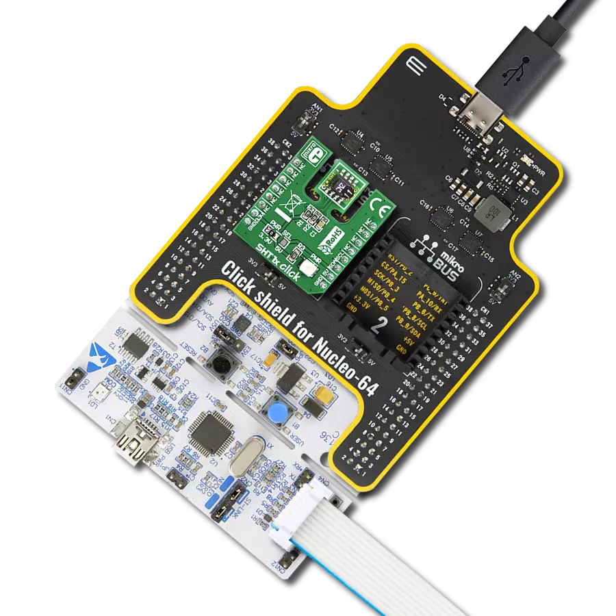
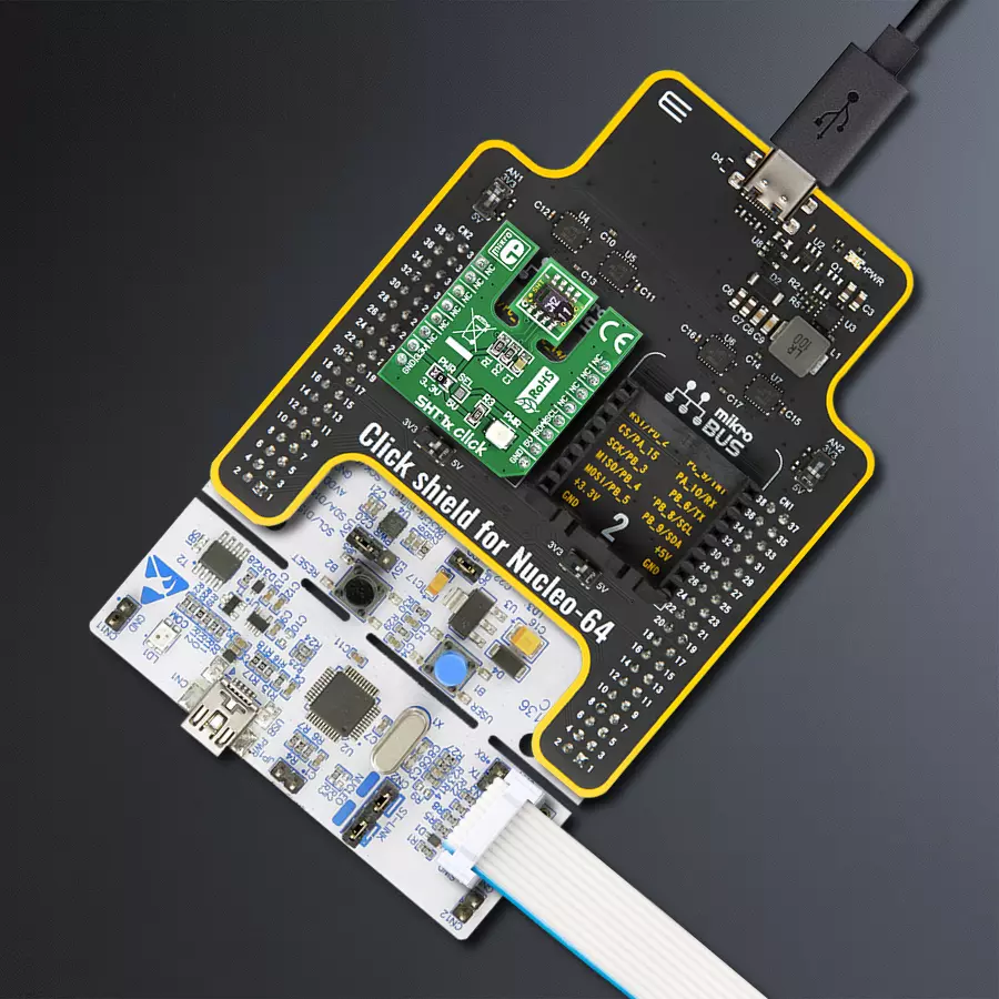
Click Shield for Nucleo-64 comes equipped with two proprietary mikroBUS™ sockets, allowing all the Click board™ devices to be interfaced with the STM32 Nucleo-64 board with no effort. This way, Mikroe allows its users to add any functionality from our ever-growing range of Click boards™, such as WiFi, GSM, GPS, Bluetooth, ZigBee, environmental sensors, LEDs, speech recognition, motor control, movement sensors, and many more. More than 1537 Click boards™, which can be stacked and integrated, are at your disposal. The STM32 Nucleo-64 boards are based on the microcontrollers in 64-pin packages, a 32-bit MCU with an ARM Cortex M4 processor operating at 84MHz, 512Kb Flash, and 96KB SRAM, divided into two regions where the top section represents the ST-Link/V2 debugger and programmer while the bottom section of the board is an actual development board. These boards are controlled and powered conveniently through a USB connection to program and efficiently debug the Nucleo-64 board out of the box, with an additional USB cable connected to the USB mini port on the board. Most of the STM32 microcontroller pins are brought to the IO pins on the left and right edge of the board, which are then connected to two existing mikroBUS™ sockets. This Click Shield also has several switches that perform functions such as selecting the logic levels of analog signals on mikroBUS™ sockets and selecting logic voltage levels of the mikroBUS™ sockets themselves. Besides, the user is offered the possibility of using any Click board™ with the help of existing bidirectional level-shifting voltage translators, regardless of whether the Click board™ operates at a 3.3V or 5V logic voltage level. Once you connect the STM32 Nucleo-64 board with our Click Shield for Nucleo-64, you can access hundreds of Click boards™, working with 3.3V or 5V logic voltage levels.

Used MCU Pins
mikroBUS™ mapper
Take a closer look
Click board™ Schematic

Step by step
Project assembly
Start by selecting your development board and Click board™. Begin with the Nucleo-64 with STM32F091RC MCU as your development board.


Software Support
Library Description
This library contains API for SHT1x Click driver.
Key functions:
sht1x_output_sda- Set pin on output.sht1x_input_sda- Set pin on input.sht1x_sda_high- Set SDA high function.
Open Source
Code example
The complete application code and a ready-to-use project are available through the NECTO Studio Package Manager for direct installation in the NECTO Studio. The application code can also be found on the MIKROE GitHub account.
/*!
 * \file
 * \brief SHT1x Click example
 *
 * # Description
 * This Click measures temperature and humidity.
 *
 * The demo application is composed of two sections :
 *
 * ## Application Init
 * Initialization driver enables GPIO.
 *
 * ## Application Task
 * This example demonstrates the use of SHT1x Click board by measuring
   temperature and humidity, and displays the results on USART terminal.
 *
 *
 * \author MikroE Team
 *
 */
// ------------------------------------------------------------------- INCLUDES

#include "board.h"
#include "log.h"
#include "sht1x.h"

// ------------------------------------------------------------------ VARIABLES

static sht1x_t sht1x;
static log_t logger;

static sht1x_cfg_t cfg;

static uint8_t i;
static uint8_t data_val;
static uint8_t err;
static uint8_t msb;
static uint8_t lsb;
static uint8_t checksum;
static uint16_t t;
static uint16_t h;
static float value;
static uint8_t uc_sens_err;
static int16_t int_temp;
static int16_t int_humi;
static float humidity;
static float temperature;

// ------------------------------------------------------ APPLICATION FUNCTIONS

void sht1x_trans_start ( )
{
    sht1x_output_sda ( &sht1x, &cfg );

    sht1x_sda_high( &sht1x );

    sht1x_input_sda ( &sht1x, &cfg );

    sht1x_scl_low( &sht1x );

    Delay_us( 1 );

    sht1x_scl_high( &sht1x );

    Delay_us( 1 );

    sht1x_output_sda ( &sht1x, &cfg );

    sht1x_sda_low( &sht1x );

    Delay_us( 1 );

    sht1x_scl_low( &sht1x );

    Delay_us( 3 );

    sht1x_scl_high( &sht1x );

    Delay_us( 1 );

    sht1x_input_sda ( &sht1x, &cfg );

    Delay_us( 1 );

    sht1x_scl_low( &sht1x );
}

uint8_t sht1x_read_byte( uint8_t ack )
{
    i = 0x80;
    data_val = 0;

    sht1x_output_sda ( &sht1x, &cfg );

    sht1x_sda_high( &sht1x );

    sht1x_input_sda ( &sht1x, &cfg );

    sht1x_scl_low( &sht1x );

    while( i )
    {
        sht1x_scl_high( &sht1x );
        Delay_us( 1 );
        if ( sht1x_get_sda( &sht1x ) == 1 )
        {
            data_val = ( data_val | i );
        }
        sht1x_scl_low( &sht1x );
        Delay_us( 1 );
        i = ( i >> 1 );
    }

    sht1x_output_sda ( &sht1x, &cfg );

    if( ack )
    {
        sht1x_sda_low( &sht1x );
    }
    else
    {
        sht1x_sda_high( &sht1x );
    }

    sht1x_scl_high( &sht1x );
    Delay_us( 3 );
    sht1x_scl_low( &sht1x );
    Delay_us( 1 );

    sht1x_sda_high( &sht1x );

    sht1x_input_sda ( &sht1x, &cfg );

    return data_val;
}

uint8_t sht1x_write_byte( uint8_t value )
{
    i = 0x80;
    err = 0;

    sht1x_output_sda ( &sht1x, &cfg );

    while( i )
    {
        if ( i & value )
        {
            sht1x_sda_high( &sht1x );
        }
        else
        {
            sht1x_sda_low( &sht1x );
        }

        sht1x_scl_high( &sht1x );
        Delay_us( 3 );
        sht1x_scl_low( &sht1x );
        Delay_us( 3 );
        i = ( i >> 1 );
    }

    sht1x_sda_high( &sht1x );
    sht1x_input_sda ( &sht1x, &cfg );

    sht1x_scl_high( &sht1x );
    Delay_us( 3 );
    if ( sht1x_get_sda( &sht1x ) == 1 )
	{
	    err = 1;
	}
    Delay_us( 1 );
    sht1x_scl_low( &sht1x );

    return err;
}

uint8_t sht1x_measure( uint16_t *p_val, uint8_t mode )
{
    i = 0;
    *p_val = 0;

    sht1x_trans_start(  );

    if( mode )
    {
        mode = SHT1X_MEAS_HUMI;
    }
    else
    {
        mode = SHT1X_MEAS_TEMP;
    }

    if( sht1x_write_byte( mode ) )
    {
        return( 1 );
    }

    sht1x_input_sda ( &sht1x, &cfg );

    while( i < 240 )
    {
        Delay_ms ( 3 );
        if ( sht1x_get_sda( &sht1x ) == 0 )
        {
            i = 0;
            break;
        }
        i++;
    }

    if( i )
    {
        return( 2 );
    }

    msb = sht1x_read_byte( SHT1X_ACK );
    lsb = sht1x_read_byte( SHT1X_ACK );
    checksum = sht1x_read_byte( SHT1X_NACK );

    *p_val = ( msb << 8 ) | lsb ;

    return( 0 );
}

void sht1x_read_results ( float *f_t, float *f_rh )
{
    uc_sens_err = 0;

    uc_sens_err = sht1x_measure( &t, 0 );
    int_temp = ( int16_t )( sht1x_calc_temp( &sht1x, t ) * 10 );

    uc_sens_err = sht1x_measure(&h, 1);
    int_humi = ( int16_t )( sht1x_calc_humi( &sht1x, h, t ) * 10 );

    value = ( float )int_temp;
    *f_t = value / 10;
    value = ( float )int_humi;
    *f_rh = value / 10;
}

uint8_t sht1x_rd_stat_reg ( uint8_t *p_val )
{
    checksum = 0;

    sht1x_trans_start( );
    if( sht1x_write_byte( SHT1X_STAT_REG_R ) )
    {
        return 1;
    }
    *p_val = sht1x_read_byte( SHT1X_ACK );
    checksum = sht1x_read_byte( SHT1X_NACK );

    return 0;
}

uint8_t sht1x_wr_stat_reg ( uint8_t value )
{
    sht1x_trans_start();
    if( sht1x_write_byte( SHT1X_STAT_REG_W ) )
    {
        return 1;
    }
    if( sht1x_write_byte( value ) )
    {
        return 1;
    }

    return 0;
}

void sht1x_connection_reset ( )
{
    sht1x_output_sda ( &sht1x, &cfg );

    sht1x_sda_high( &sht1x );

    sht1x_input_sda ( &sht1x, &cfg );

    sht1x_scl_low( &sht1x );

    for( i = 0; i < 9; i++ )
    {
        sht1x_scl_high( &sht1x );
        Delay_us( 3 );
        sht1x_scl_low( &sht1x );
        Delay_us( 3 );
    }

    sht1x_trans_start( );
}

uint8_t sht1x_soft_reset ( )
{
    sht1x_connection_reset( );

    return ( sht1x_write_byte( SHT1X_SOFT_RESET ) );
}

void application_init ( void )
{
    log_cfg_t log_cfg;

    /**
     * Logger initialization.
     * Default baud rate: 115200
     * Default log level: LOG_LEVEL_DEBUG
     * @note If USB_UART_RX and USB_UART_TX
     * are defined as HAL_PIN_NC, you will
     * need to define them manually for log to work.
     * See @b LOG_MAP_USB_UART macro definition for detailed explanation.
     */
    LOG_MAP_USB_UART( log_cfg );
    log_init( &logger, &log_cfg );
    log_info(&logger, "---- Application Init ----");

    //  Click initialization.

    sht1x_cfg_setup( &cfg );
    SHT1X_MAP_MIKROBUS( cfg, MIKROBUS_1 );
    sht1x_init( &sht1x, &cfg );
}

void application_task ( void )
{
    sht1x_read_results( &temperature, &humidity );
    log_printf( &logger, " Temperature: %.2f ", temperature );
    log_printf( &logger, " C \r\n" );

    log_printf( &logger, " Humidity: %.2f ", humidity );
    log_printf( &logger, " \r\n" );

    Delay_ms ( 1000 );
}

int main ( void )
{
    /* Do not remove this line or clock might not be set correctly. */
    #ifdef PREINIT_SUPPORTED
    preinit();
    #endif

    application_init( );

    for ( ; ; )
    {
        application_task( );
    }

    return 0;
}

// ------------------------------------------------------------------------ END
Additional Support
Resources
Category:Temperature & humidity


