Ensure you're always in the comfort zone using 2521020222501 and STM32F091RC
Stay cool or get cozy with our temperature monitoring magic!
Published Feb 26, 2024
Click board™
Thermo 18 Click
Dev. board
Nucleo-64 with STM32F091RC MCU
Compiler
NECTO Studio
MCU
STM32F091RC
Our innovative temperature monitoring solution ensures your utmost comfort and well-being by providing accurate temperature data for your space, whether aiming for a cozy home environment or a comfortable workspace.
A
A
Hardware Overview
How does it work?
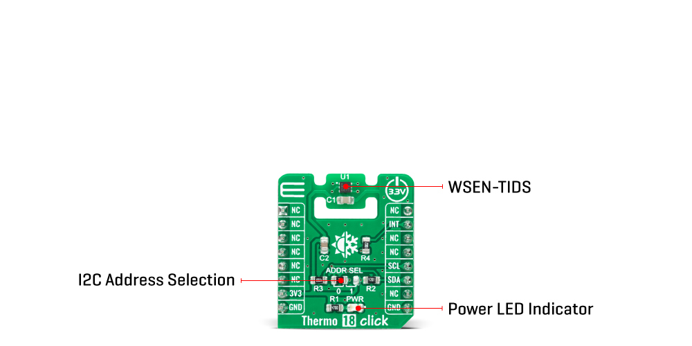
Thermo 18 Click is based on the WSEN-TIDS (2521020222501), a silicon-based, high-resolution digital temperature sensor from Würth Elektronik. This temperature sensor is characterized by high accuracy; a temperature range of -40°C to +125°C provides ±0.5°C accuracy, while a range of -10°C to +60°C it goes down to ±0.25°C. WSEN-TIDS sensor is factory-calibrated and can be used without time-consuming re-measurements. It features a 16-bit output signal that can be read out via an I2C serial interface with output data rates up to a maximum of 200Hz. This Click board™ can be configured in the following operational modes: Power-down mode, Single conversion mode, and Continuous mode. In Power-down mode, the digital chain that samples the temperature data is turned off, and the current consumption is at its minimum. Before entering this mode, the
temperature data registers retain the last sampled temperature value. However, serial communication with the host controller via the I2C bus is still possible, allowing the user to configure the device by accessing the control and temperature threshold registers. The Single conversion mode can activate when the sensor is still in a Power-down mode, allowing a single temperature measurement to be performed according to the request of the host controller, while the continuous mode constantly samples new temperature measurements and writes the data to the temperature data registers. Once the device is configured in one of the operating modes, temperature values are sampled and stored in the temperature data registers, available for the user to read. Thermo 18 Click communicates with MCU using the standard I2C
2-Wire interface with a frequency of 400kHz in Fast Mode and up to 1MHz in Fast Mode Plus. Also, the WSEN-TIDS features an interrupt signal routed on the INT pin of the mikroBUS™ socket, which indicates when a new set of measured temperature data is available, simplifying data synchronization in the digital system that uses the device. Besides, it also allows the choice of the least significant bit of its I2C slave address by positioning the SMD jumper labeled ADDR SEL to an appropriate position marked as 0 and 1. This Click board™ can be operated only with a 3.3V logic voltage level. The board must perform appropriate logic voltage level conversion before using MCUs with different logic levels. Also, it comes equipped with a library containing functions and an example code that can be used as a reference for further development.
Features overview
Development board
Nucleo-64 with STM32F091RC MCU offers a cost-effective and adaptable platform for developers to explore new ideas and prototype their designs. This board harnesses the versatility of the STM32 microcontroller, enabling users to select the optimal balance of performance and power consumption for their projects. It accommodates the STM32 microcontroller in the LQFP64 package and includes essential components such as a user LED, which doubles as an ARDUINO® signal, alongside user and reset push-buttons, and a 32.768kHz crystal oscillator for precise timing operations. Designed with expansion and flexibility in mind, the Nucleo-64 board features an ARDUINO® Uno V3 expansion connector and ST morpho extension pin
headers, granting complete access to the STM32's I/Os for comprehensive project integration. Power supply options are adaptable, supporting ST-LINK USB VBUS or external power sources, ensuring adaptability in various development environments. The board also has an on-board ST-LINK debugger/programmer with USB re-enumeration capability, simplifying the programming and debugging process. Moreover, the board is designed to simplify advanced development with its external SMPS for efficient Vcore logic supply, support for USB Device full speed or USB SNK/UFP full speed, and built-in cryptographic features, enhancing both the power efficiency and security of projects. Additional connectivity is
provided through dedicated connectors for external SMPS experimentation, a USB connector for the ST-LINK, and a MIPI® debug connector, expanding the possibilities for hardware interfacing and experimentation. Developers will find extensive support through comprehensive free software libraries and examples, courtesy of the STM32Cube MCU Package. This, combined with compatibility with a wide array of Integrated Development Environments (IDEs), including IAR Embedded Workbench®, MDK-ARM, and STM32CubeIDE, ensures a smooth and efficient development experience, allowing users to fully leverage the capabilities of the Nucleo-64 board in their projects.

Microcontroller Overview
MCU Card / MCU

Architecture
ARM Cortex-M0
MCU Memory (KB)
256
Silicon Vendor
STMicroelectronics
Pin count
64
RAM (Bytes)
32768
You complete me!
Accessories
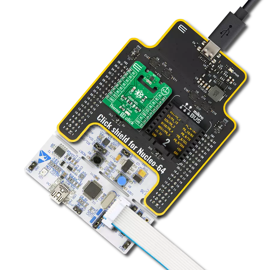
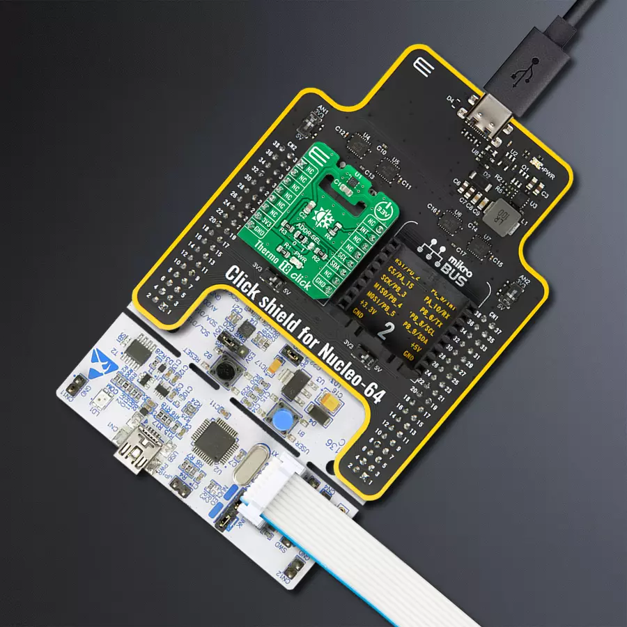
Click Shield for Nucleo-64 comes equipped with two proprietary mikroBUS™ sockets, allowing all the Click board™ devices to be interfaced with the STM32 Nucleo-64 board with no effort. This way, Mikroe allows its users to add any functionality from our ever-growing range of Click boards™, such as WiFi, GSM, GPS, Bluetooth, ZigBee, environmental sensors, LEDs, speech recognition, motor control, movement sensors, and many more. More than 1537 Click boards™, which can be stacked and integrated, are at your disposal. The STM32 Nucleo-64 boards are based on the microcontrollers in 64-pin packages, a 32-bit MCU with an ARM Cortex M4 processor operating at 84MHz, 512Kb Flash, and 96KB SRAM, divided into two regions where the top section represents the ST-Link/V2 debugger and programmer while the bottom section of the board is an actual development board. These boards are controlled and powered conveniently through a USB connection to program and efficiently debug the Nucleo-64 board out of the box, with an additional USB cable connected to the USB mini port on the board. Most of the STM32 microcontroller pins are brought to the IO pins on the left and right edge of the board, which are then connected to two existing mikroBUS™ sockets. This Click Shield also has several switches that perform functions such as selecting the logic levels of analog signals on mikroBUS™ sockets and selecting logic voltage levels of the mikroBUS™ sockets themselves. Besides, the user is offered the possibility of using any Click board™ with the help of existing bidirectional level-shifting voltage translators, regardless of whether the Click board™ operates at a 3.3V or 5V logic voltage level. Once you connect the STM32 Nucleo-64 board with our Click Shield for Nucleo-64, you can access hundreds of Click boards™, working with 3.3V or 5V logic voltage levels.

Used MCU Pins
mikroBUS™ mapper
Take a closer look
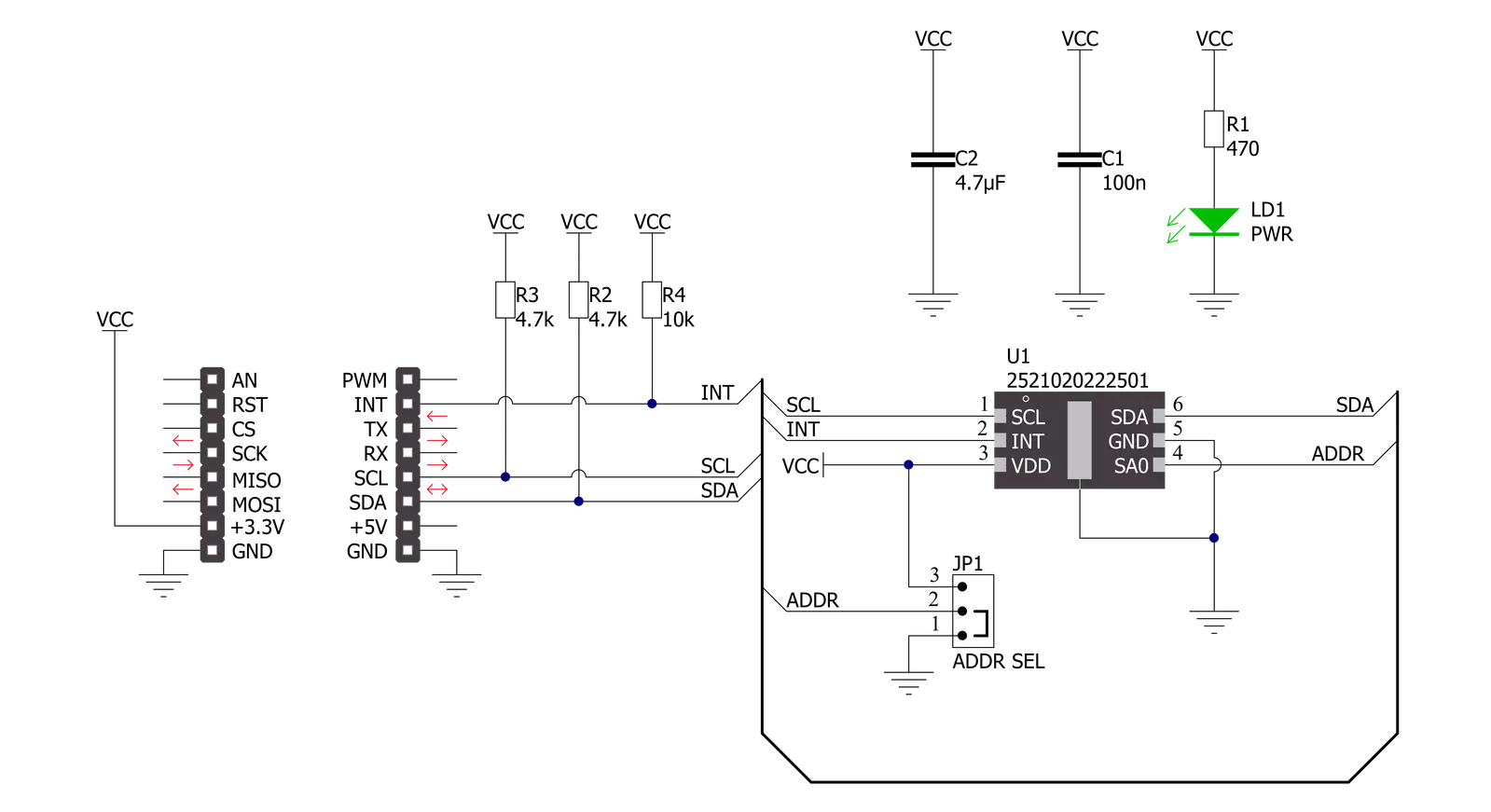
Click board™ Schematic
Step by step
Project assembly
Start by selecting your development board and Click board™. Begin with the Nucleo-64 with STM32F091RC MCU as your development board.


Software Support
Library Description
This library contains API for Thermo 18 Click driver.
Key functions:
thermo18_read_temperature- Reads and calculates temperature value.thermo18_set_temperature_threshold- Sets temperature threshold.thermo18_reset- Resets device.
Open Source
Code example
The complete application code and a ready-to-use project are available through the NECTO Studio Package Manager for direct installation in the NECTO Studio. The application code can also be found on the MIKROE GitHub account.
/*!
 * @file main.c
 * @brief Thermo18 Click example
 *
 * # Description
 * The example application showcases ability of device
 * to read temperature and detect and assert interrupt
 * on undertemperature or overtemperature thresholds.
 *
 * The demo application is composed of two sections :
 *
 * ## Application Init
 * Initialization of communication modules and interrupt pin.
 * Reads device ID to check comunication. Then resets device,
 * and sets undertemperature and overtemperature thresholds
 * on 24 and 30 degrees Celsius. In the end enables OneShot
 * temperature conversion.
 *
 * ## Application Task
 * Checks status to see if the temperature conversion is finished.
 * When it's finished reads and logs calculated temperature data.
 * Then checks if status is asserted for threshold detection, and
 * logs if detected. In the end re-enables OneShot conversion.
 *
 * @author Luka FIlipovic
 *
 */

#include "board.h"
#include "log.h"
#include "thermo18.h"

static thermo18_t thermo18;
static log_t logger;

void application_init ( void )
{
    log_cfg_t log_cfg;  /**< Logger config object. */
    thermo18_cfg_t thermo18_cfg;  /**< Click config object. */

    /**
     * Logger initialization.
     * Default baud rate: 115200
     * Default log level: LOG_LEVEL_DEBUG
     * @note If USB_UART_RX and USB_UART_TX
     * are defined as HAL_PIN_NC, you will
     * need to define them manually for log to work.
     * See @b LOG_MAP_USB_UART macro definition for detailed explanation.
     */
    LOG_MAP_USB_UART( log_cfg );
    log_init( &logger, &log_cfg );
    log_info( &logger, " Application Init " );

    // Click initialization.
    thermo18_cfg_setup( &thermo18_cfg );
    THERMO18_MAP_MIKROBUS( thermo18_cfg, MIKROBUS_1 );
    err_t init_flag = thermo18_init( &thermo18, &thermo18_cfg );
    if ( I2C_MASTER_ERROR == init_flag )
    {
        log_error( &logger, " Application Init Error. " );
        log_info( &logger, " Please, run program again... " );
        for ( ; ; );
    }

    uint8_t temp_data = 0;
    thermo18_generic_read( &thermo18, THERMO18_REG_DEVICE_ID, &temp_data );
    log_printf( &logger, " > ID: 0x%.2X\r\n", ( uint16_t )temp_data );

    if ( THERMO18_DEVICE_ID != temp_data )
    {
        log_error( &logger, " Device ID. " );
        log_info( &logger, " Please, run program again... " );
        for ( ; ; );
    }

    if ( thermo18_default_cfg ( &thermo18 ) )
    {
        log_error( &logger, " Default configuration. " );
        log_info( &logger, " Please, run program again... " );
        for ( ; ; );
    }

    Delay_ms ( 1000 );
    Delay_ms ( 1000 );
    //One shot reading
    thermo18_generic_write( &thermo18, THERMO18_REG_CTRL, THERMO18_CONTROL_ONESHOT_ENABLED );

    log_info( &logger, " Application Task " );
}

void application_task ( void )
{
    uint8_t status;
    thermo18_generic_read( &thermo18, THERMO18_REG_STATUS, &status );
    //Check if data is ready
    if ( THERMO18_STATUS_DATA_READY == ( status & THERMO18_STATUS_DATA_BUSY ) )
    {
        //Temperature reading
        float temp = 0.0;
        thermo18_read_temperature( &thermo18, &temp );
        log_printf( &logger, " > Temperature[degC]: %.2f\r\n", temp );
        //Check threshold
        if ( 0 != status )
        {
            if ( THERMO18_STATUS_OVERTEMPERATURE == status )
            {
                log_info( &logger, " Overtemperature Threshold detected." );
            }
            else if ( THERMO18_STATUS_UNDERTEMPERATURE == status )
            {
                log_info( &logger, " Undertemperature Threshold detected." );
            }
        }
        //Re-Enable One shot reading
        thermo18_generic_write( &thermo18, THERMO18_REG_CTRL, THERMO18_CONTROL_ONESHOT_ENABLED );
    }

    Delay_ms ( 300 );
}

int main ( void )
{
    /* Do not remove this line or clock might not be set correctly. */
    #ifdef PREINIT_SUPPORTED
    preinit();
    #endif

    application_init( );

    for ( ; ; )
    {
        application_task( );
    }

    return 0;
}

// ------------------------------------------------------------------------ END
Additional Support
Resources
Category:Temperature & humidity


