Provide superior illumination with CAT3224 and TM4C129ENCPDT
Your beacon of light in the dark
Published Sep 09, 2023
Click board™
LED Flash Click
Dev. board
Fusion for Tiva v8
Compiler
NECTO Studio
MCU
TM4C129ENCPDT
With a focus on innovation and illumination, our purpose is to empower individuals with a cutting-edge LED flashlight solution that ensures longer-lasting and brighter light when you need it most
A
A
Hardware Overview
How does it work?
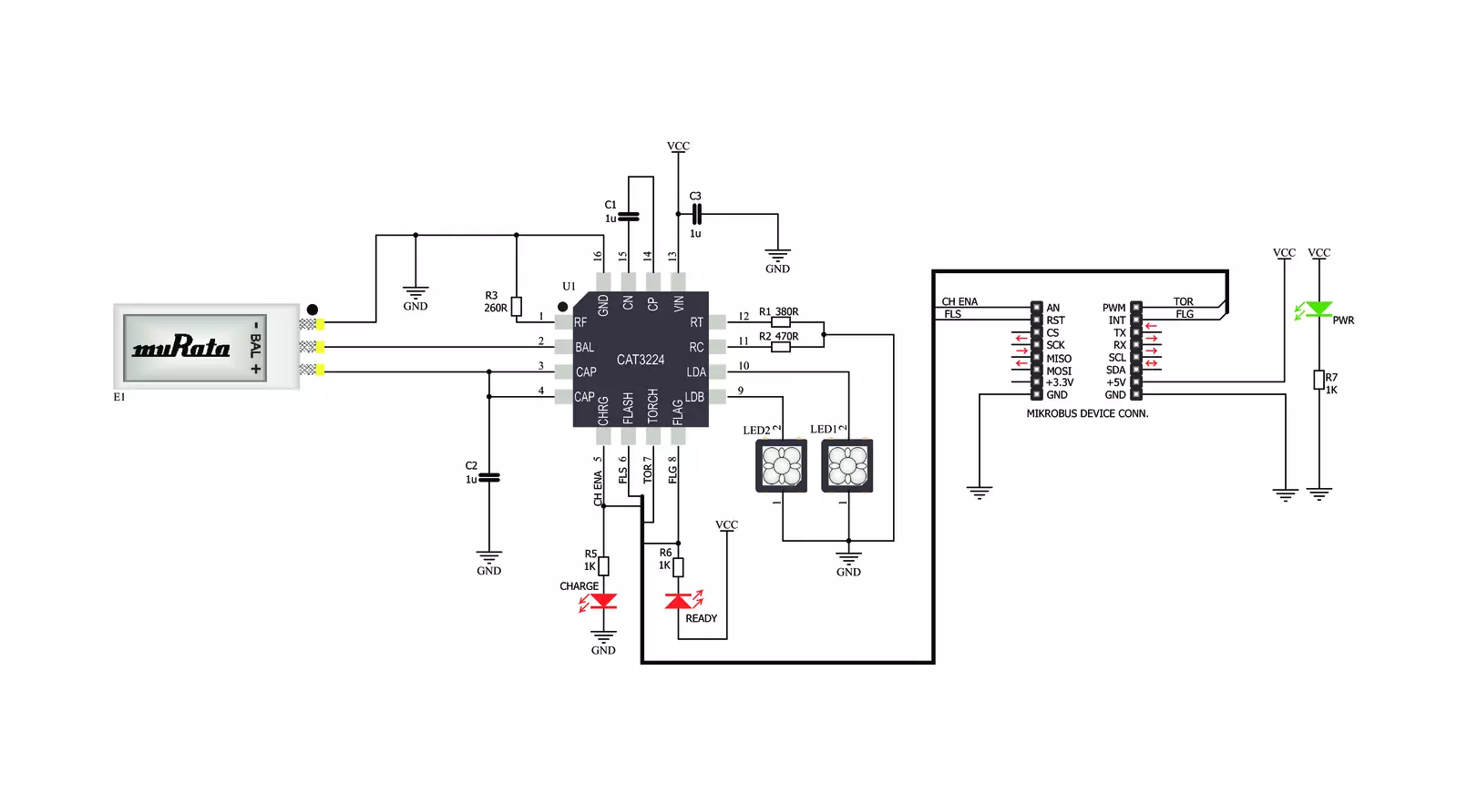
LED Flash Click is based on the CAT3224, a flash LED driver from ON Semiconductor. The click is designed to run on a 5V power supply. It communicates with the target microcontroller over the following pins on the mikroBUS™ line: AN, RST, PWM, and INT. The CAT3224 is a very high−current integrated flash LED driver which also supports the charging function for a dual−cell supercapacitor applications. Ideal for Li−ion battery−powered systems, it delivers up to 4A LED flash pulses, far beyond the peak current capability of the battery. Dual−mode 1x/2x charge pump charges the stacked supercapacitor to a nominal voltage of 5.4 V, while an active balance control circuit ensures that both capacitor cell voltages remain matched. The driver also features two matched current sources. External resistors
provide the adjustment for the maximum flash mode current (up to 4 A) and the torch mode current (up to 400 mA). A built−in safety timer automatically terminates the flash pulse beyond a maximum duration of 300 ms. The CAT3224 has a shutdown mode that is so low that ON Semiconductor can safely call it "zero" mode. In this mode, it typically uses only 1μA. On the LED Flash click there are three different LED indicators, here is how they operate: CHARGE — When this LED is on the driver is in charge mode; READY — When this LED is on it indicates that the supercapacitor is fully charged; PWR — Indicates if power is present. FLAG is an active−low open−drain output that notifies the microcontroller that the supercapacitor is fully charged by pulling the output low (pin 15 in the
mikroBUS). When using FLAG, this pin should be connected to a positive rail via an external pull−up resistor. TORCH is the torch mode enable pin. When high, the LED current sources are enabled in torch mode. FLASH is the flash mode enable pin. When high, the LED current sources are enabled in flash mode. If FLASH is kept high for longer than 300 ms typical, the LED channels are automatically disabled. LEDA, LEDB are connected internally to the current sources and must be connected to the LED anodes. Each output is independently current regulated. These pins enter a high−impedance ‘zero’ current state whenever the device is placed in shutdown mode or FLASH and TORCH are low.


Features overview
Development board
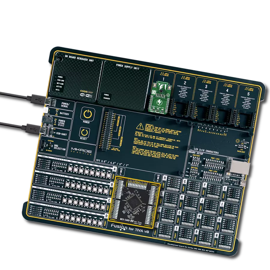
Fusion for TIVA v8 is a development board specially designed for the needs of rapid development of embedded applications. It supports a wide range of microcontrollers, such as different 32-bit ARM® Cortex®-M based MCUs from Texas Instruments, regardless of their number of pins, and a broad set of unique functions, such as the first-ever embedded debugger/programmer over a WiFi network. The development board is well organized and designed so that the end-user has all the necessary elements, such as switches, buttons, indicators, connectors, and others, in one place. Thanks to innovative manufacturing technology, Fusion for TIVA v8 provides a fluid and immersive working experience, allowing access
anywhere and under any circumstances at any time. Each part of the Fusion for TIVA v8 development board contains the components necessary for the most efficient operation of the same board. An advanced integrated CODEGRIP programmer/debugger module offers many valuable programming/debugging options, including support for JTAG, SWD, and SWO Trace (Single Wire Output)), and seamless integration with the Mikroe software environment. Besides, it also includes a clean and regulated power supply module for the development board. It can use a wide range of external power sources, including a battery, an external 12V power supply, and a power source via the USB Type-C (USB-C) connector.
Communication options such as USB-UART, USB HOST/DEVICE, CAN (on the MCU card, if supported), and Ethernet is also included. In addition, it also has the well-established mikroBUS™ standard, a standardized socket for the MCU card (SiBRAIN standard), and two display options for the TFT board line of products and character-based LCD. Fusion for TIVA v8 is an integral part of the Mikroe ecosystem for rapid development. Natively supported by Mikroe software tools, it covers many aspects of prototyping and development thanks to a considerable number of different Click boards™ (over a thousand boards), the number of which is growing every day.

Microcontroller Overview
MCU Card / MCU

Type
8th Generation
Architecture
ARM Cortex-M4
MCU Memory (KB)
1024
Silicon Vendor
Texas Instruments
Pin count
128
RAM (Bytes)
262144
Used MCU Pins
mikroBUS™ mapper
Take a closer look
Click board™ Schematic
Step by step
Project assembly

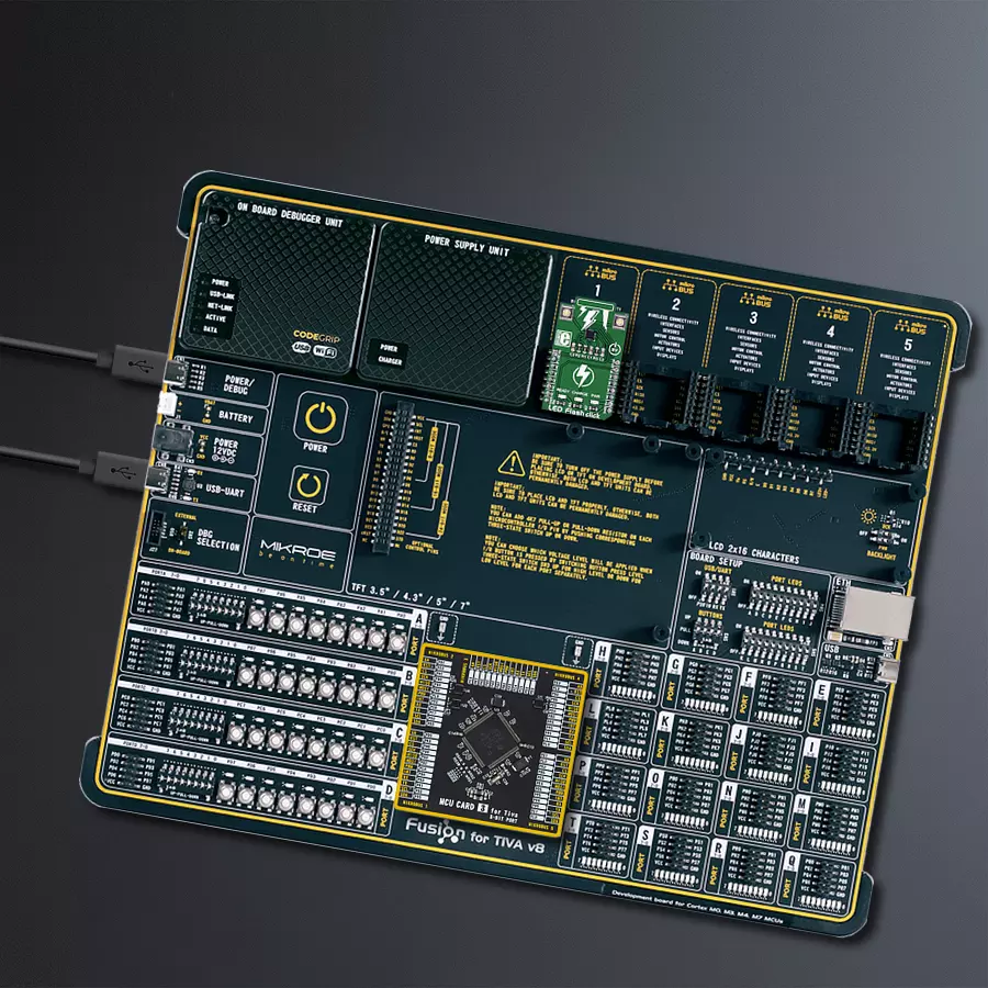
Start by selecting your development board and Click board™. Begin with the Fusion for Tiva v8 as your development board.


Software Support
Library Description
This library contains API for LED Flash Click driver.
Key functions:
ledflash_char_supcap_enable- Charge Supercapacitor Enable functionledflash_flash_enable- Flash Enable functionledflash_flash_rdy_flag- Check Flash Ready Flag function
Open Source
Code example
The complete application code and a ready-to-use project are available through the NECTO Studio Package Manager for direct installation in the NECTO Studio. The application code can also be found on the MIKROE GitHub account.
/*!
 * \file
 * \brief LED Flash Click example
 *
 * # Description
 * This application switching on and off led flash.
 *
 * The demo application is composed of two sections :
 *
 * ## Application Init
 * Initialization driver enables GPIO, starts write log and issues a warning.
 *
 * ## Application Task
 * This example demonstrates the use of LED Flash Click board by flashing
 * with LEDs when ever supercapacitor is at a full voltage.
 *
 * \author MikroE Team
 *
 */
// ------------------------------------------------------------------- INCLUDES

#include "board.h"
#include "log.h"
#include "ledflash.h"

// ------------------------------------------------------------------ VARIABLES

static ledflash_t ledflash;
static log_t logger;

// ------------------------------------------------------ APPLICATION FUNCTIONS

void application_init ( void )
{
    log_cfg_t log_cfg;
    ledflash_cfg_t cfg;

    /**
     * Logger initialization.
     * Default baud rate: 115200
     * Default log level: LOG_LEVEL_DEBUG
     * @note If USB_UART_RX and USB_UART_TX
     * are defined as HAL_PIN_NC, you will
     * need to define them manually for log to work.
     * See @b LOG_MAP_USB_UART macro definition for detailed explanation.
     */
    LOG_MAP_USB_UART( log_cfg );
    log_init( &logger, &log_cfg );
    log_info( &logger, "---- Application Init ----" );

    //  Click initialization.

    ledflash_cfg_setup( &cfg );
    LEDFLASH_MAP_MIKROBUS( cfg, MIKROBUS_1 );
    ledflash_init( &ledflash, &cfg );
    Delay_ms ( 100 );

    log_printf( &logger, "----------------------------------\r\n" );
    log_printf( &logger, " LED Flash Click \r\n" );
    log_printf( &logger, "----------------------------------\r\n" );
    log_printf( &logger, "/////////////////\r\n" );
    log_printf( &logger, " WARNING!!! \r\n" );
    log_printf( &logger, " DO NOT LOOK \r\n" );
    log_printf( &logger, " INTO THE LEDS, \r\n" );
    log_printf( &logger, " WHILE THAY ARE ON!!! \r\n" );
    log_printf( &logger, "/////////////////\r\n" );
    Delay_ms ( 1000 );
}

void application_task (  )
{
    uint8_t state;

    log_printf( &logger, " Charge Supercapacitor Enable \r\n" );
    ledflash_char_supcap_enable( &ledflash );
    Delay_ms ( 1000 );
    state = ledflash_flash_rdy_flag( &ledflash );

    if ( state == 0 )
    {
        log_printf( &logger, " Flash ON! \r\n" );
        ledflash_flash_enable( &ledflash );
    }
    else
    {
        log_printf( &logger, " Flash OFF! \r\n" );
        ledflash_flash_disable( &ledflash );
    }
    log_printf( &logger, "----------------------------------\r\n" );
}

int main ( void )
{
    /* Do not remove this line or clock might not be set correctly. */
    #ifdef PREINIT_SUPPORTED
    preinit();
    #endif

    application_init( );

    for ( ; ; )
    {
        application_task( );
    }

    return 0;
}

// ------------------------------------------------------------------------ END
Additional Support
Resources
Category:LED Segment


