Add small, blue, readable displays to various electronic projects with JSS-3011BUB-21, TLC5947 and PIC32MZ2048EFM100
Useful for things like digital clocks, scoreboards, or any device where you need to show information clearly
Published Feb 21, 2024
Click board™
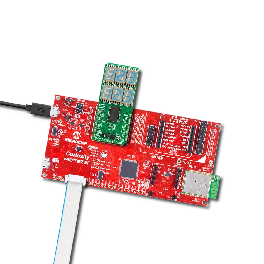
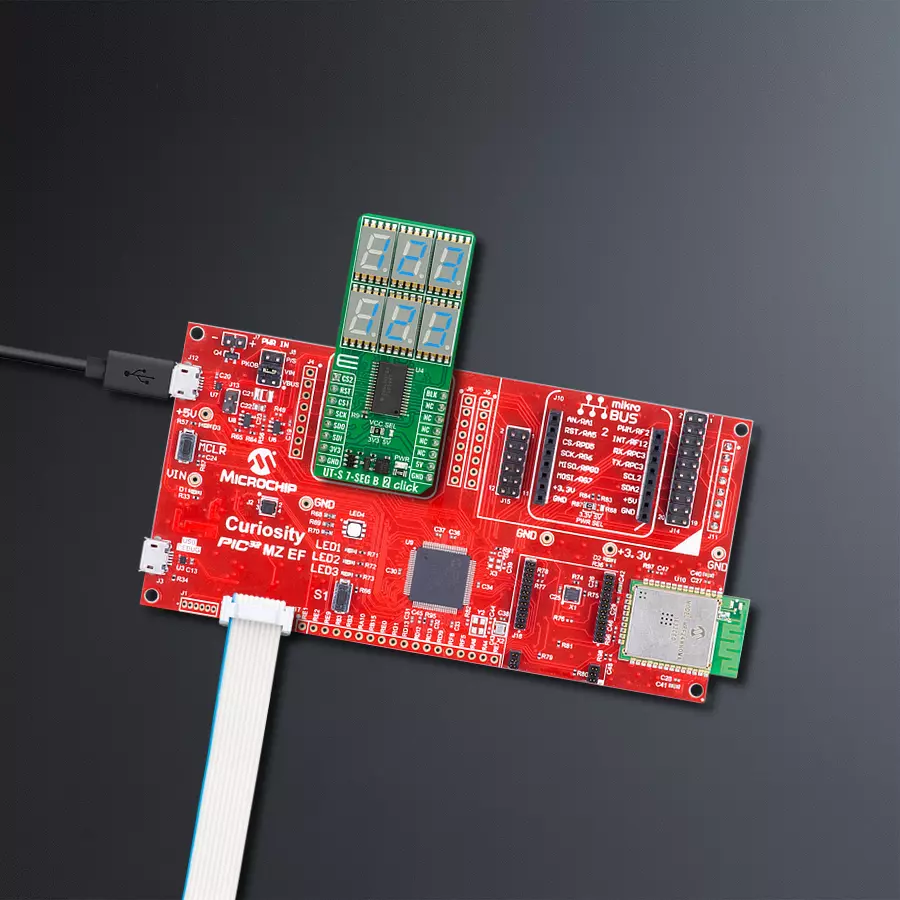
UT-S 7-SEG B 2 Click
Dev. board
Curiosity PIC32 MZ EF
Compiler
NECTO Studio
MCU
PIC32MZ2048EFM100
Six ultra-thin displays capable of showing numbers, letters, and symbols in blue, making the information easy to read
A
A
Hardware Overview
How does it work?
UT-S 7-SEG B 2 Click is based on the TLC5947, a constant-current sink LED driver from Texas Instruments, alongside six ultra-thin blue single-digit numeric displays, the JSS-3011BUB-21. This high-intensity and reliable blue source color device is made with Indium-Gallium-Nitride light-emitting diode conducting material. It features low current operation, high light output, excellent character appearance, and is mechanically rugged. The display can work on 5V and 3.3V and has a common anode as its internal design. It consists
of seven blue LED segments that form an 8 number and the eighth segment as a decimal point, or DP. The communication between the host MCU and the UT-S 7-SEG B 2 Click is established via two TLC5947s, 24-channel 12-bit constant-current sink LED drivers from Analog Devices. This driver has a 4-wire serial interface using four inputs and a data output. The output-enable input (BLK) gates to all 24 outputs ON and OFF and is fast enough to be used as a PWM input for LED intensity control. The constant-current outputs are programmed together
to around 12mA using a single external resistor. This Click board™ can operate with either 3.3V or 5V logic voltage levels selected via the VCC SEL jumper. This way, both 3.3V and 5V capable MCUs can use the communication lines properly. Also, this Click board™ comes equipped with a library containing easy-to-use functions and an example code that can be used as a reference for further development.

Features overview
Development board
Curiosity PIC32 MZ EF development board is a fully integrated 32-bit development platform featuring the high-performance PIC32MZ EF Series (PIC32MZ2048EFM) that has a 2MB Flash, 512KB RAM, integrated FPU, Crypto accelerator, and excellent connectivity options. It includes an integrated programmer and debugger, requiring no additional hardware. Users can expand
functionality through MIKROE mikroBUS™ Click™ adapter boards, add Ethernet connectivity with the Microchip PHY daughter board, add WiFi connectivity capability using the Microchip expansions boards, and add audio input and output capability with Microchip audio daughter boards. These boards are fully integrated into PIC32’s powerful software framework, MPLAB Harmony,
which provides a flexible and modular interface to application development a rich set of inter-operable software stacks (TCP-IP, USB), and easy-to-use features. The Curiosity PIC32 MZ EF development board offers expansion capabilities making it an excellent choice for a rapid prototyping board in Connectivity, IOT, and general-purpose applications.

Microcontroller Overview
MCU Card / MCU

Architecture
PIC32
MCU Memory (KB)
2048
Silicon Vendor
Microchip
Pin count
100
RAM (Bytes)
524288
Used MCU Pins
mikroBUS™ mapper
Take a closer look
Click board™ Schematic

Step by step
Project assembly

Start by selecting your development board and Click board™. Begin with the Curiosity PIC32 MZ EF as your development board.


Software Support
Library Description
This library contains API for UT-S 7-SEG B 2 Click driver.
Key functions:
uts7segb2_display_number- This function displays the desired number and brightness on the selected segmentsuts7segb2_display_character- This function displays the desired characters and brightness on the selected segmentsuts7segb2_set_led_output- This function sets the LED driver output
Open Source
Code example
The complete application code and a ready-to-use project are available through the NECTO Studio Package Manager for direct installation in the NECTO Studio. The application code can also be found on the MIKROE GitHub account.
/*!
 * @file main.c
 * @brief UT-S 7-SEG B 2 Click example
 *
 * # Description
 * This example demonstrates the use of the UT-S 7-SEG B 2 Click board
 * by writing and displaying the desired numbers on the screen.
 *
 * The demo application is composed of two sections :
 *
 * ## Application Init
 * Initialization of SPI module and log UART.
 * After driver initialization, the app executes a default configuration.
 *
 * ## Application Task
 * The demo application draws numbers, in hexadecimal format,
 * from 0h to FFFh on the top segment group and from FFFh to 0h on the bottom segment group.
 * Results are being sent to the UART Terminal, where you can track their changes.
 *
 * @author Mikroe Team
 *
 */

#include "board.h"
#include "log.h"
#include "uts7segb2.h"

static uts7segb2_t uts7segb2;
static log_t logger;
static uts7segb2_number_cfg_t number;

void application_init ( void )
{
    log_cfg_t log_cfg;  /**< Logger config object. */
    uts7segb2_cfg_t uts7segb2_cfg;  /**< Click config object. */

    /**
     * Logger initialization.
     * Default baud rate: 115200
     * Default log level: LOG_LEVEL_DEBUG
     * @note If USB_UART_RX and USB_UART_TX
     * are defined as HAL_PIN_NC, you will
     * need to define them manually for log to work.
     * See @b LOG_MAP_USB_UART macro definition for detailed explanation.
     */
    LOG_MAP_USB_UART( log_cfg );
    log_init( &logger, &log_cfg );
    log_info( &logger, " Application Init " );

    // Click initialization.
    uts7segb2_cfg_setup( &uts7segb2_cfg );
    UTS7SEGB2_MAP_MIKROBUS( uts7segb2_cfg, MIKROBUS_1 );
    if ( SPI_MASTER_ERROR == uts7segb2_init( &uts7segb2, &uts7segb2_cfg ) )
    {
        log_error( &logger, " Communication init." );
        for ( ; ; );
    }

    if ( UTS7SEGB2_ERROR == uts7segb2_default_cfg ( &uts7segb2 ) )
    {
        log_error( &logger, " Default configuration." );
        for ( ; ; );
    }

    number.brightness_top = UTS7SEGB2_BRIGHTNESS_DEFAULT;
    number.brightness_bottom = UTS7SEGB2_BRIGHTNESS_DEFAULT;
    number.base = UTS7SEGB2_BASE_NUM_SYS_HEXADECIMAL;
    number.dot_bit_mask = UTS7SEGB2_TOP_SEG_NO_DOT | UTS7SEGB2_BOTTOM_SEG_NO_DOT;
    log_info( &logger, " Application Task " );
    Delay_ms ( 100 );
}

void application_task ( void )
{
    for ( uint16_t num_cnt = 0; num_cnt <= UTS7SEGB2_HEXADECIMAL_NUM_MAX; num_cnt++ )
    {
        number.num_top = num_cnt;
        number.num_bottom = UTS7SEGB2_HEXADECIMAL_NUM_MAX - num_cnt;
        if ( UTS7SEGB2_OK == uts7segb2_display_number( &uts7segb2, number ) )
        {
            log_printf( &logger, " %.3X\r\n", number.num_top );
            log_printf( &logger, " %.3X\r\n\n", number.num_bottom );
            Delay_ms ( 100 );
        }
    }
    log_printf( &logger, " --------------\r\n\n" );
    Delay_ms ( 1000 );
}

int main ( void )
{
    /* Do not remove this line or clock might not be set correctly. */
    #ifdef PREINIT_SUPPORTED
    preinit();
    #endif

    application_init( );

    for ( ; ; )
    {
        application_task( );
    }

    return 0;
}

// ------------------------------------------------------------------------ END
Additional Support
Resources
Category:LED Segment


