Be confident in your hardware's capabilities thanks to AMC80 and PIC18F45K42
Peak performance - no compromises!

Published Nov 11, 2023
Click board™
HW Monitor 2 Click
Dev.Board
EasyPIC v8
Compiler
NECTO Studio
MCU
PIC18F45K42
Redefine the way you monitor hardware – our solution is the key to unlocking unparalleled performance, setting new standards for excellence.
A
A
Hardware Overview
How does it work?
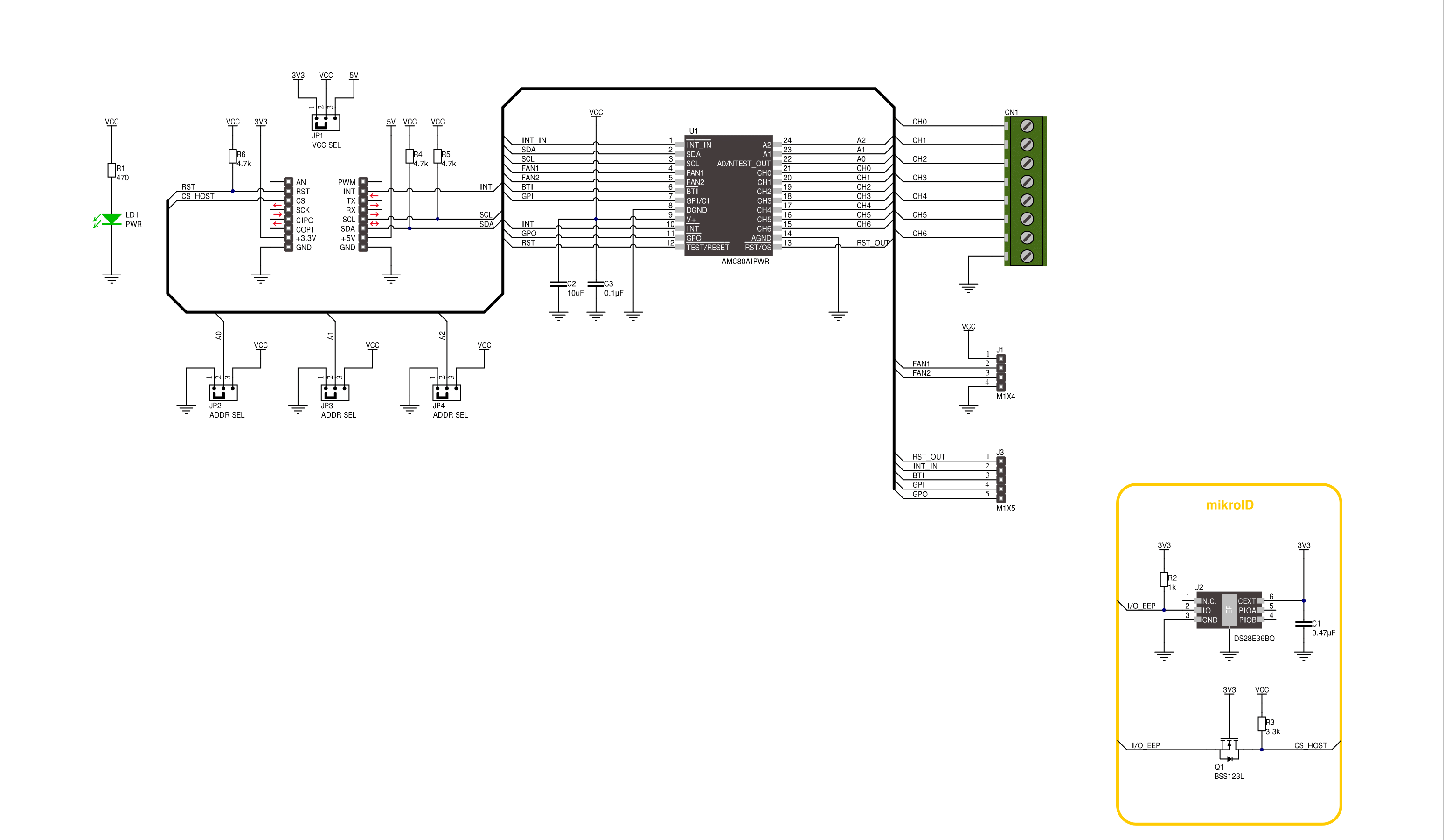
HW Monitor 2 Click is based on the AMC80, a system hardware monitor from Texas Instruments that performs power supply, temperature, and fan monitoring for various embedded systems. The AMC80 provides seven analog inputs spread across the terminals on the top of the board labeled from CH0 to CH6, a temperature sensor, an ADC, two fan speed counters, and various inputs and outputs on a single chip. It continuously converts analog inputs to 10-bit resolution with a 2.5mV LSB, yielding input ranges of 0 to 2.56V. The analog inputs are intended to be connected to the several power supplies present in a typical communications infrastructure system. This Click board™ communicates with MCU using the standard I2C 2-Wire interface to read data and configure settings with a maximum frequency of 400kHz. The AMC80 includes an analog filter on the I2C lines that improves noise immunity and supports the timeout reset function on SDA and SCL pins, preventing I2C bus lockup. Also, the AMC80 allows choosing the least significant bits (LSB) of its I2C slave address using the SMD jumpers labeled ADDR SEL. The AMC80 is especially suited to interface with linear and digital
temperature sensors such as TMP75 via the BTI pin on the left unpopulated header. Temperature can be converted to a 9-bit or 12-bit two's complement word with resolutions of 0.5°C or 0.0625°C LSB, respectively. On the same header, in addition to the BTI pin, there is also a GPI pin, which, in addition to its function as a general-purpose input pin, can also serve as a chassis intrusion detection input. The chassis intrusion input is designed to accept an active high signal from an external circuit that latches, such as when the cover is removed from the computer. Next in this board's additional features are an external interrupt input INT IN, a master reset for external purposes RST O, and a single power switch pin GPO. The INT IN active low interrupt provides a way to chain the interrupts from other devices through the AMC80 to the host, the RST O is intended to provide a master reset to devices connected to this line, while the GPO pin is an active low NMOS open drain output intended to drive an external power PMOS for software power control or can be utilized to control power to a cooling fan. The AMC80 also possesses a general reset signal routed on the RST pin of the mikroBUS™ socket to reset the AMC80,
and an additional interrupt signal, routed on the INT pin of the mikroBUS™ socket whenever some of the external interrupts like INT_OUT, interrupt from the temperature sensor, or when a chassis detection event occurs. The right-side header contains the fan inputs, labeled F1 and F2, that can be programmed to accept either fan failure indicator programmed to be active high or active low or tachometer signals. Fan inputs measure the period of tachometer pulses from the fans, providing a higher count for lower fan speeds. The full-scale fan counts are 255 (8-bit counter), representing a stopped or slow fan. Based on a count of 153, nominal speeds are programmable from 1100 to 8800 RPM. Signal conditioning circuitry is also included to accommodate the slow rise and fall times. This Click board™ can operate with either 3.3V or 5V logic voltage levels selected via the VCC SEL jumper. This way, both 3.3V and 5V capable MCUs can use the communication lines properly. Also, this Click board™ comes equipped with a library containing easy-to-use functions and an example code that can be used as a reference for further development.

Features overview
Development board
EasyPIC v8 is a development board specially designed for the needs of rapid development of embedded applications. It supports many high pin count 8-bit PIC microcontrollers from Microchip, regardless of their number of pins, and a broad set of unique functions, such as the first-ever embedded debugger/programmer. The development board is well organized and designed so that the end-user has all the necessary elements, such as switches, buttons, indicators, connectors, and others, in one place. Thanks to innovative manufacturing technology, EasyPIC v8 provides a fluid and immersive working experience, allowing access anywhere and under any
circumstances at any time. Each part of the EasyPIC v8 development board contains the components necessary for the most efficient operation of the same board. In addition to the advanced integrated CODEGRIP programmer/debugger module, which offers many valuable programming/debugging options and seamless integration with the Mikroe software environment, the board also includes a clean and regulated power supply module for the development board. It can use a wide range of external power sources, including a battery, an external 12V power supply, and a power source via the USB Type-C (USB-C) connector.
Communication options such as USB-UART, USB DEVICE, and CAN are also included, including the well-established mikroBUS™ standard, two display options (graphical and character-based LCD), and several different DIP sockets. These sockets cover a wide range of 8-bit PIC MCUs, from the smallest PIC MCU devices with only eight up to forty pins. EasyPIC v8 is an integral part of the Mikroe ecosystem for rapid development. Natively supported by Mikroe software tools, it covers many aspects of prototyping and development thanks to a considerable number of different Click boards™ (over a thousand boards), the number of which is growing every day.

Microcontroller Overview
MCU Card / MCU
Architecture
PIC
MCU Memory (KB)
32
Silicon Vendor
Microchip
Pin count
40
RAM (Bytes)
2048
Used MCU Pins
mikroBUS™ mapper
Take a closer look
Schematic
Step by step
Project assembly

Start by selecting your development board and Click board™. Begin with the EasyPIC v8 as your development board.


Track your results in real time
Application Output
After pressing the "FLASH" button on the left-side panel, it is necessary to open the UART terminal to display the achieved results. By clicking on the Tools icon in the right-hand panel, multiple different functions are displayed, among which is the UART Terminal. Click on the offered "UART Terminal" icon.

Once the UART terminal is opened, the window takes on a new form. At the top of the tab are two buttons, one for adjusting the parameters of the UART terminal and the other for connecting the UART terminal. The tab's lower part is reserved for displaying the achieved results. Before connecting, the terminal has a Disconnected status, indicating that the terminal is not yet active. Before connecting, it is necessary to check the set parameters of the UART terminal. Click on the "OPTIONS" button.

In the newly opened UART Terminal Options field, we check if the terminal settings are correct, such as the set port and the Baud rate of UART communication. If the data is not displayed properly, it is possible that the Baud rate value is not set correctly and needs to be adjusted to 115200. If all the parameters are set correctly, click on "CONFIGURE".

The next step is to click on the "CONNECT" button, after which the terminal status changes from Disconnected to Connected in green, and the data is displayed in the Received data field.

Software Support
Library Description
This library contains API for HW Monitor 2 Click driver.
Key functions:
hwmonitor2_get_analog_inputs- HW Monitor 2 gets analog inputs voltage function.hwmonitor2_get_temperature- HW Monitor 2 gets temperature function.hwmonitor2_set_config- HW Monitor 2 set the configuration function.
Open Source
Code example
This example can be found in NECTO Studio. Feel free to download the code, or you can copy the code below.
/*!
 * @file main.c
 * @brief HW Monitor 2 Click example
 *
 * # Description
 * This example demonstrates the use of the HW Monitor 2 Click board™.
 * The demo application monitors analog voltage inputs and local temperature data.
 *
 * The demo application is composed of two sections :
 *
 * ## Application Init
 * The initialization of the I2C module, log UART and additional pins.
 * After the driver init, the app executes a default configuration.
 *
 * ## Application Task
 * This example displays the Analog Voltage Inputs from CH0 to CH6 [mV]
 * and Temperature [degree Celsius] data.
 * Results are being sent to the UART Terminal, where you can track their changes.
 *
 * @author Nenad Filipovic
 *
 */

#include "board.h"
#include "log.h"
#include "hwmonitor2.h"

static hwmonitor2_t hwmonitor2;
static log_t logger;

void application_init ( void )
{
    log_cfg_t log_cfg;  /**< Logger config object. */
    hwmonitor2_cfg_t hwmonitor2_cfg;  /**< Click config object. */

    /**
     * Logger initialization.
     * Default baud rate: 115200
     * Default log level: LOG_LEVEL_DEBUG
     * @note If USB_UART_RX and USB_UART_TX
     * are defined as HAL_PIN_NC, you will
     * need to define them manually for log to work.
     * See @b LOG_MAP_USB_UART macro definition for detailed explanation.
     */
    LOG_MAP_USB_UART( log_cfg );
    log_init( &logger, &log_cfg );
    log_info( &logger, " Application Init " );

    // Click initialization.
    hwmonitor2_cfg_setup( &hwmonitor2_cfg );
    HWMONITOR2_MAP_MIKROBUS( hwmonitor2_cfg, MIKROBUS_1 );
    if ( I2C_MASTER_ERROR == hwmonitor2_init( &hwmonitor2, &hwmonitor2_cfg ) )
    {
        log_error( &logger, " Communication init." );
        for ( ; ; );
    }

    if ( HWMONITOR2_ERROR == hwmonitor2_default_cfg ( &hwmonitor2 ) )
    {
        log_error( &logger, " Default configuration." );
        for ( ; ; );
    }

    log_info( &logger, " Application Task " );
    log_printf( &logger, "---------------------------\r\n" );
    Delay_ms( 1000 );
}

void application_task ( void )
{
    static float temperature, voltage;
    for ( uint8_t ch_pos = 0; ch_pos < 7; ch_pos++ )
    {
        if ( HWMONITOR2_OK == hwmonitor2_get_analog_inputs( &hwmonitor2, ch_pos, &voltage ) )
        {
            log_printf( &logger, "CH %d: %.1f mV\r\n", ( uint16_t ) ch_pos, voltage );
            Delay_ms( 100 );
        }
    }
    log_printf( &logger, "- - - - - - - - - - - - - -\r\n" );

    if ( HWMONITOR2_OK == hwmonitor2_get_temperature( &hwmonitor2, &temperature ) )
    {
        log_printf( &logger, " Temperature: %.3f [deg c]\r\n", temperature );
        Delay_ms( 100 );
    }
    log_printf( &logger, "---------------------------\r\n" );
    Delay_ms( 1000 );
}

void main ( void )
{
    application_init( );

    for ( ; ; )
    {
        application_task( );
    }
}

// ------------------------------------------------------------------------ END


