Include numerical displays in your projects, such as homemade weather stations or timers, with LDT-M2804RI and PIC18F2455
Ensure clear visibility of the displayed information

Published Feb 26, 2024
Click board™
7-SEG 2 Click
Dev. board
EasyPIC v8
Compiler
NECTO Studio
MCU
PIC18F2455
Clear and compact red displays for applications that require real-time numerical feedback, such as digital clocks or measurement tools
A
A
Hardware Overview
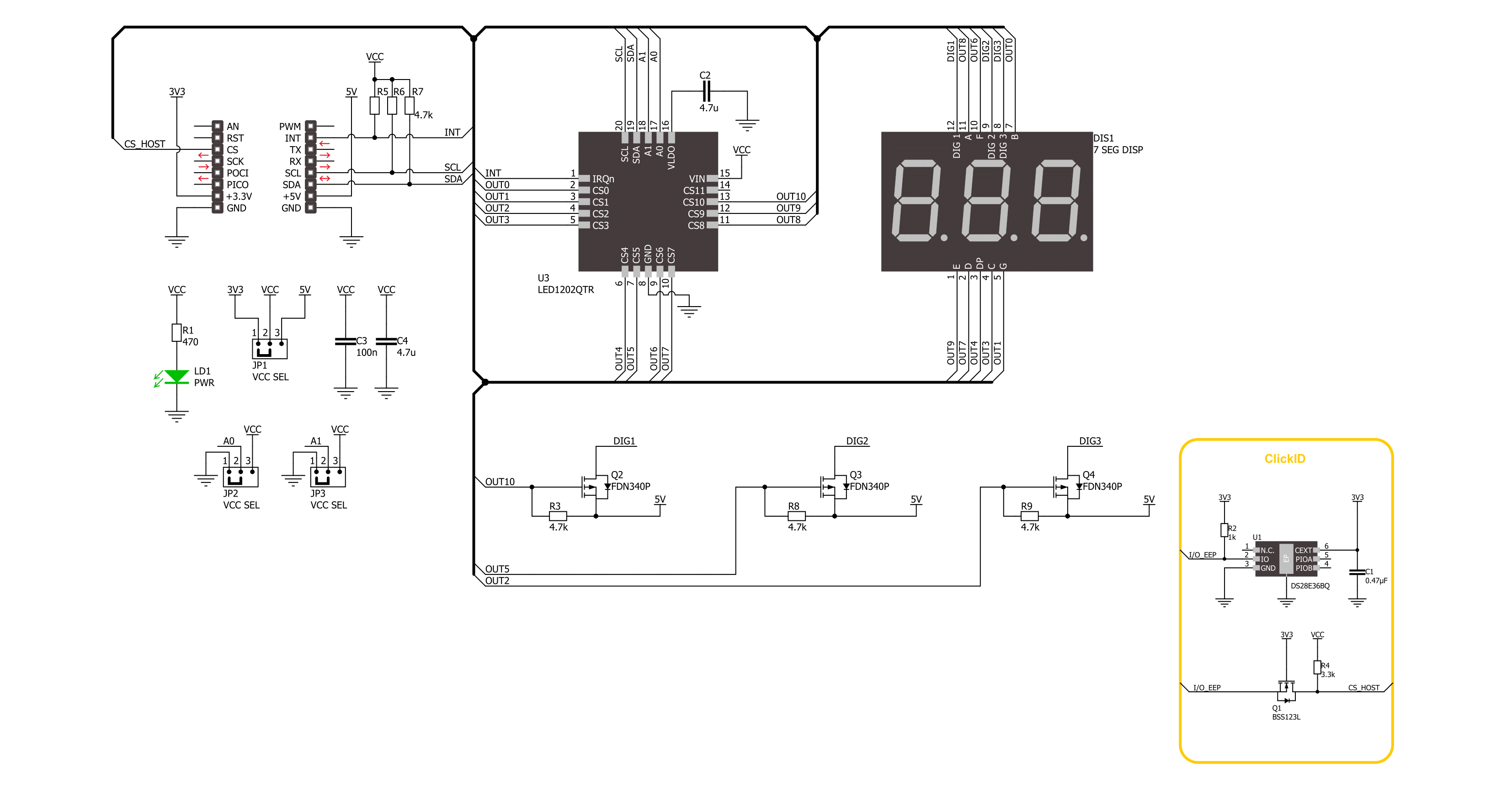
How does it work?
7-SEG 2 Click is based on the LDT-M2804RI, a three-digit seven-segment display from Lumex. The red LED segments have a common anode, a 635nm wavelength, and a luminous intensity of 5000mcd. The LED1202, a 12-channel low-quiescent current LED driver from STMicroelectronics, drives the display. The output current can be adjusted separately for each channel by a 12-bit digital dimming control. A slow turn-on and turn-off time improves the system's low noise generation performance; moreover, the
phase shifting function helps to reduce the inrush current. Eight patterns can be stored in the driver for automatic sequencing without MCU intervention. 7-SEG 2 Click uses a standard 2-wire I2C communication from the LED driver to allow the host MCU to control the seven-segment display. The I2C interface supports clock frequencies of up to 400kHz. The I2C address can be selected over the ADDR SEL jumpers. The interrupt INT pin will notify the host MCU when an interrupt event occurs. It can be an open LED detection,
overtemperature protection, the pattern fault and status interrupt, the start of frame, and more. This Click board™ can operate with either 3.3V or 5V logic voltage levels selected via the VCC SEL jumper. This way, both 3.3V and 5V capable MCUs can use the communication lines properly. Also, this Click board™ comes equipped with a library containing easy-to-use functions and an example code that can be used as a reference for further development.

Features overview
Development board
EasyPIC v8 is a development board specially designed for the needs of rapid development of embedded applications. It supports many high pin count 8-bit PIC microcontrollers from Microchip, regardless of their number of pins, and a broad set of unique functions, such as the first-ever embedded debugger/programmer. The development board is well organized and designed so that the end-user has all the necessary elements, such as switches, buttons, indicators, connectors, and others, in one place. Thanks to innovative manufacturing technology, EasyPIC v8 provides a fluid and immersive working experience, allowing access anywhere and under any
circumstances at any time. Each part of the EasyPIC v8 development board contains the components necessary for the most efficient operation of the same board. In addition to the advanced integrated CODEGRIP programmer/debugger module, which offers many valuable programming/debugging options and seamless integration with the Mikroe software environment, the board also includes a clean and regulated power supply module for the development board. It can use a wide range of external power sources, including a battery, an external 12V power supply, and a power source via the USB Type-C (USB-C) connector.
Communication options such as USB-UART, USB DEVICE, and CAN are also included, including the well-established mikroBUS™ standard, two display options (graphical and character-based LCD), and several different DIP sockets. These sockets cover a wide range of 8-bit PIC MCUs, from the smallest PIC MCU devices with only eight up to forty pins. EasyPIC v8 is an integral part of the Mikroe ecosystem for rapid development. Natively supported by Mikroe software tools, it covers many aspects of prototyping and development thanks to a considerable number of different Click boards™ (over a thousand boards), the number of which is growing every day.

Microcontroller Overview
MCU Card / MCU

Architecture
PIC
MCU Memory (KB)
24
Silicon Vendor
Microchip
Pin count
28
RAM (Bytes)
2048
Used MCU Pins
mikroBUS™ mapper
Take a closer look
Click board™ Schematic
Step by step
Project assembly

Start by selecting your development board and Click board™. Begin with the EasyPIC v8 as your development board.


Software Support
Library Description
This library contains API for 7-SEG 2 Click driver.
Key functions:
c7seg2_set_segments_current- This function is used to set the current value of the segment's ledsc7seg2_write_segment- This function is used to write a number [0..9] to a selected segment [0..2] with or w/o a decimal pointerc7seg2_write_number- This function is used to write a number [0..999] to a selected segment [0..2] with or w/o a decimal pointer
Open Source
Code example
The complete application code and a ready-to-use project are available through the NECTO Studio Package Manager for direct installation in the NECTO Studio. The application code can also be found on the MIKROE GitHub account.
/*!
 * @file main.c
 * @brief 7-SEG 2 Click example
 *
 * # Description
 * The example demonstrates the use of the 7-SEG 2 Click board by displaying
 * a counter number [0.00-9.99] which is incremented by 0.01 at a desired rate.
 *
 * The demo application is composed of two sections :
 *
 * ## Application Init
 * Initializes the driver and performs default configuration, sets the device
 * in output enabled mode and checks communication by reading device ID.
 *
 * ## Application Task
 * Writes a counter number [0.00-9.99] to the display as frequently as possible.
 * The displayed counter value is incremented by 0.01 at a rate defined with
 * the C7SEG2_NUM_COUNTER_RATE macro.
 *
 * @author MikroE Team
 *
 */

#include "board.h"
#include "log.h"
#include "c7seg2.h"

// Number of display updates (see 7-SEG 2 refresh rate setting) before the displayed counter is incremented.
#define C7SEG2_NUM_COUNTER_RATE             10

static c7seg2_t c7seg2;
static log_t logger;

void application_init ( void )
{
    log_cfg_t log_cfg;  /**< Logger config object. */
    c7seg2_cfg_t c7seg2_pnp_cfg;  /**< Click config object. */

    /**
     * Logger initialization.
     * Default baud rate: 115200
     * Default log level: LOG_LEVEL_DEBUG
     * @note If USB_UART_RX and USB_UART_TX
     * are defined as HAL_PIN_NC, you will
     * need to define them manually for log to work.
     * See @b LOG_MAP_USB_UART macro definition for detailed explanation.
     */
    LOG_MAP_USB_UART( log_cfg );
    log_init( &logger, &log_cfg );
    log_info( &logger, " Application Init " );

    // Click initialization.
    c7seg2_cfg_setup( &c7seg2_pnp_cfg );
    C7SEG2_MAP_MIKROBUS( c7seg2_pnp_cfg, MIKROBUS_1 );
    if ( I2C_MASTER_ERROR == c7seg2_init( &c7seg2, &c7seg2_pnp_cfg ) )
    {
        log_error( &logger, " Communication init." );
        for ( ; ; );
    }

    uint8_t device_id = 0;
    c7seg2_read_reg( &c7seg2, C7SEG2_REG_DEVICE_ID, &device_id );
    if ( C7SEG2_DEVICE_ID != device_id )
    {
        log_error( &logger, " Communication error." );
        for ( ; ; );
    }

    if ( C7SEG2_ERROR == c7seg2_default_cfg ( &c7seg2 ) )
    {
        log_error( &logger, " Default configuration." );
        for ( ; ; );
    }

    log_info( &logger, " Application Task " );
}

void application_task ( void )
{
    static uint16_t counter = 0;
    static uint16_t time = 0;

    c7seg2_write_number( &c7seg2, counter, C7SEG2_DP_AT_SEGMENT_2 );

    if ( ++time >= C7SEG2_NUM_COUNTER_RATE )
    {
        if ( ++counter > C7SEG2_MAX_NUMBER )
        {
            counter = 0;
        }
        time = 0;
    }
}

int main ( void )
{
    /* Do not remove this line or clock might not be set correctly. */
    #ifdef PREINIT_SUPPORTED
    preinit();
    #endif

    application_init( );

    for ( ; ; )
    {
        application_task( );
    }

    return 0;
}

// ------------------------------------------------------------------------ END


