Provide superior illumination with CAT3224 and PIC18F57Q43
Your beacon of light in the dark
Published Feb 13, 2024
Click board™
LED Flash Click
Dev. board
Curiosity Nano with PIC18F57Q43
Compiler
NECTO Studio
MCU
PIC18F57Q43
With a focus on innovation and illumination, our purpose is to empower individuals with a cutting-edge LED flashlight solution that ensures longer-lasting and brighter light when you need it most
A
A
Hardware Overview
How does it work?
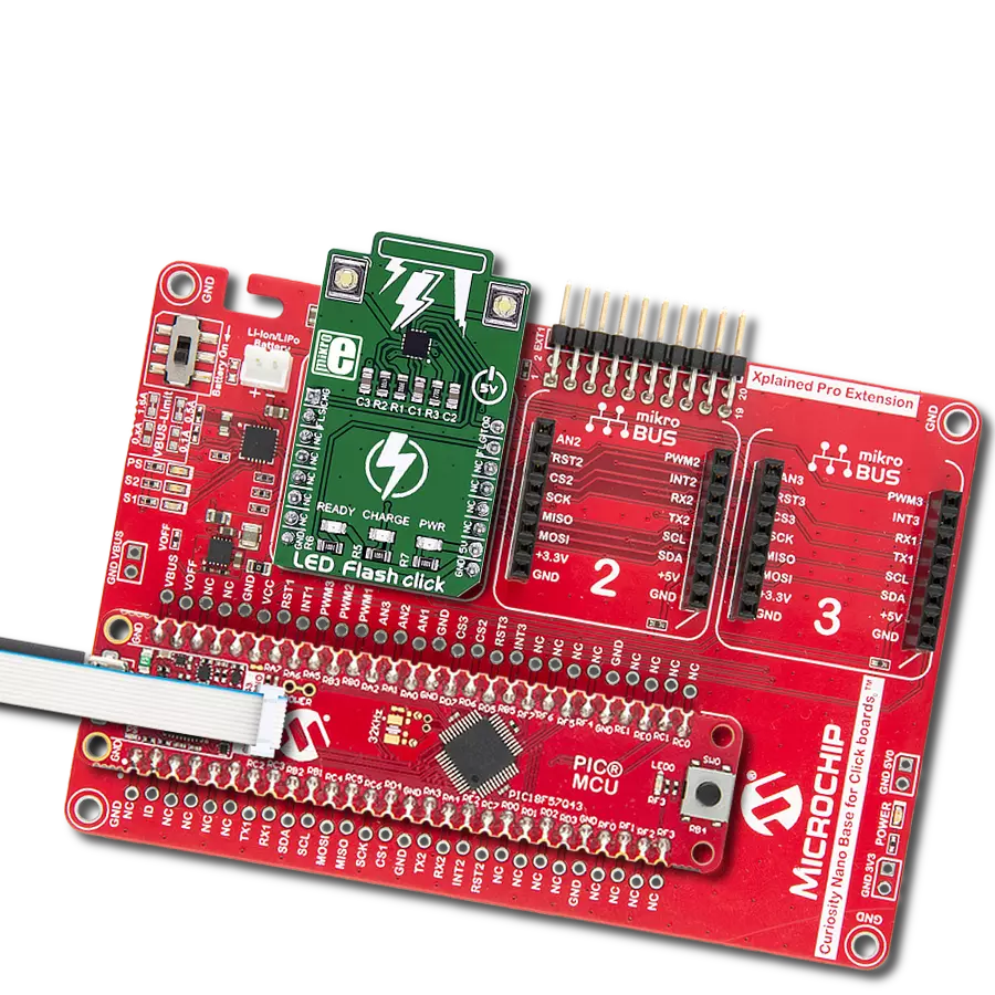
LED Flash Click is based on the CAT3224, a flash LED driver from ON Semiconductor. The click is designed to run on a 5V power supply. It communicates with the target microcontroller over the following pins on the mikroBUS™ line: AN, RST, PWM, and INT. The CAT3224 is a very high−current integrated flash LED driver which also supports the charging function for a dual−cell supercapacitor applications. Ideal for Li−ion battery−powered systems, it delivers up to 4A LED flash pulses, far beyond the peak current capability of the battery. Dual−mode 1x/2x charge pump charges the stacked supercapacitor to a nominal voltage of 5.4 V, while an active balance control circuit ensures that both capacitor cell voltages remain matched. The driver also features two matched current sources. External resistors
provide the adjustment for the maximum flash mode current (up to 4 A) and the torch mode current (up to 400 mA). A built−in safety timer automatically terminates the flash pulse beyond a maximum duration of 300 ms. The CAT3224 has a shutdown mode that is so low that ON Semiconductor can safely call it "zero" mode. In this mode, it typically uses only 1μA. On the LED Flash click there are three different LED indicators, here is how they operate: CHARGE — When this LED is on the driver is in charge mode; READY — When this LED is on it indicates that the supercapacitor is fully charged; PWR — Indicates if power is present. FLAG is an active−low open−drain output that notifies the microcontroller that the supercapacitor is fully charged by pulling the output low (pin 15 in the
mikroBUS). When using FLAG, this pin should be connected to a positive rail via an external pull−up resistor. TORCH is the torch mode enable pin. When high, the LED current sources are enabled in torch mode. FLASH is the flash mode enable pin. When high, the LED current sources are enabled in flash mode. If FLASH is kept high for longer than 300 ms typical, the LED channels are automatically disabled. LEDA, LEDB are connected internally to the current sources and must be connected to the LED anodes. Each output is independently current regulated. These pins enter a high−impedance ‘zero’ current state whenever the device is placed in shutdown mode or FLASH and TORCH are low.


Features overview
Development board
PIC18F57Q43 Curiosity Nano evaluation kit is a cutting-edge hardware platform designed to evaluate microcontrollers within the PIC18-Q43 family. Central to its design is the inclusion of the powerful PIC18F57Q43 microcontroller (MCU), offering advanced functionalities and robust performance. Key features of this evaluation kit include a yellow user LED and a responsive
mechanical user switch, providing seamless interaction and testing. The provision for a 32.768kHz crystal footprint ensures precision timing capabilities. With an onboard debugger boasting a green power and status LED, programming and debugging become intuitive and efficient. Further enhancing its utility is the Virtual serial port (CDC) and a debug GPIO channel (DGI
GPIO), offering extensive connectivity options. Powered via USB, this kit boasts an adjustable target voltage feature facilitated by the MIC5353 LDO regulator, ensuring stable operation with an output voltage ranging from 1.8V to 5.1V, with a maximum output current of 500mA, subject to ambient temperature and voltage constraints.

Microcontroller Overview
MCU Card / MCU

Architecture
PIC
MCU Memory (KB)
128
Silicon Vendor
Microchip
Pin count
48
RAM (Bytes)
8196
You complete me!
Accessories
Curiosity Nano Base for Click boards is a versatile hardware extension platform created to streamline the integration between Curiosity Nano kits and extension boards, tailored explicitly for the mikroBUS™-standardized Click boards and Xplained Pro extension boards. This innovative base board (shield) offers seamless connectivity and expansion possibilities, simplifying experimentation and development. Key features include USB power compatibility from the Curiosity Nano kit, alongside an alternative external power input option for enhanced flexibility. The onboard Li-Ion/LiPo charger and management circuit ensure smooth operation for battery-powered applications, simplifying usage and management. Moreover, the base incorporates a fixed 3.3V PSU dedicated to target and mikroBUS™ power rails, alongside a fixed 5.0V boost converter catering to 5V power rails of mikroBUS™ sockets, providing stable power delivery for various connected devices.

Used MCU Pins
mikroBUS™ mapper
Take a closer look
Click board™ Schematic
Step by step
Project assembly

Start by selecting your development board and Click board™. Begin with the Curiosity Nano with PIC18F57Q43 as your development board.


Software Support
Library Description
This library contains API for LED Flash Click driver.
Key functions:
ledflash_char_supcap_enable- Charge Supercapacitor Enable functionledflash_flash_enable- Flash Enable functionledflash_flash_rdy_flag- Check Flash Ready Flag function
Open Source
Code example
The complete application code and a ready-to-use project are available through the NECTO Studio Package Manager for direct installation in the NECTO Studio. The application code can also be found on the MIKROE GitHub account.
/*!
 * \file
 * \brief LED Flash Click example
 *
 * # Description
 * This application switching on and off led flash.
 *
 * The demo application is composed of two sections :
 *
 * ## Application Init
 * Initialization driver enables GPIO, starts write log and issues a warning.
 *
 * ## Application Task
 * This example demonstrates the use of LED Flash Click board by flashing
 * with LEDs when ever supercapacitor is at a full voltage.
 *
 * \author MikroE Team
 *
 */
// ------------------------------------------------------------------- INCLUDES

#include "board.h"
#include "log.h"
#include "ledflash.h"

// ------------------------------------------------------------------ VARIABLES

static ledflash_t ledflash;
static log_t logger;

// ------------------------------------------------------ APPLICATION FUNCTIONS

void application_init ( void )
{
    log_cfg_t log_cfg;
    ledflash_cfg_t cfg;

    /**
     * Logger initialization.
     * Default baud rate: 115200
     * Default log level: LOG_LEVEL_DEBUG
     * @note If USB_UART_RX and USB_UART_TX
     * are defined as HAL_PIN_NC, you will
     * need to define them manually for log to work.
     * See @b LOG_MAP_USB_UART macro definition for detailed explanation.
     */
    LOG_MAP_USB_UART( log_cfg );
    log_init( &logger, &log_cfg );
    log_info( &logger, "---- Application Init ----" );

    //  Click initialization.

    ledflash_cfg_setup( &cfg );
    LEDFLASH_MAP_MIKROBUS( cfg, MIKROBUS_1 );
    ledflash_init( &ledflash, &cfg );
    Delay_ms ( 100 );

    log_printf( &logger, "----------------------------------\r\n" );
    log_printf( &logger, " LED Flash Click \r\n" );
    log_printf( &logger, "----------------------------------\r\n" );
    log_printf( &logger, "/////////////////\r\n" );
    log_printf( &logger, " WARNING!!! \r\n" );
    log_printf( &logger, " DO NOT LOOK \r\n" );
    log_printf( &logger, " INTO THE LEDS, \r\n" );
    log_printf( &logger, " WHILE THAY ARE ON!!! \r\n" );
    log_printf( &logger, "/////////////////\r\n" );
    Delay_ms ( 1000 );
}

void application_task (  )
{
    uint8_t state;

    log_printf( &logger, " Charge Supercapacitor Enable \r\n" );
    ledflash_char_supcap_enable( &ledflash );
    Delay_ms ( 1000 );
    state = ledflash_flash_rdy_flag( &ledflash );

    if ( state == 0 )
    {
        log_printf( &logger, " Flash ON! \r\n" );
        ledflash_flash_enable( &ledflash );
    }
    else
    {
        log_printf( &logger, " Flash OFF! \r\n" );
        ledflash_flash_disable( &ledflash );
    }
    log_printf( &logger, "----------------------------------\r\n" );
}

int main ( void )
{
    /* Do not remove this line or clock might not be set correctly. */
    #ifdef PREINIT_SUPPORTED
    preinit();
    #endif

    application_init( );

    for ( ; ; )
    {
        application_task( );
    }

    return 0;
}

// ------------------------------------------------------------------------ END
Additional Support
Resources
Category:LED Segment


